
2010
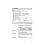

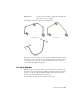


Table Of Contents
- Contents
- Part 1 Tubes and Pipes
- 1 Get Started with Tube & Pipe
- 2 Route Basics
- 3 Set Styles
- 4 Create Rigid Routes and Runs
- Workflow for Rigid Routes
- Create Auto Route Regions
- Manually Create Parametric Regions
- Automatically Dimension Route Sketches
- Create Segments With Precise Values
- Define Parallel and Perpendicular Segments
- Snap Route Points to Existing Geometry
- Place Constraints On Route Sketches
- Create Bends Between Existing Pipe Segments
- Create Pipe Routes With Custom Bends
- Create Bent Tube Routes
- Realign 3D Orthogonal Route Tool
- Control Dimension Visibility
- Populated Routes
- 5 Create and Edit Flexible Hose Routes
- 6 Edit Rigid Routes and Runs
- 7 Use Content Center Libraries
- 8 Author and Publish
- 9 Document Routes and Runs
- Part 2 Cable and Harness
- 10 Get Started with Cable and Harness
- 11 Work With Harness Assemblies
- 12 Use the Cable and Harness Library
- 13 Work with Wires and Cables
- 14 Work with Segments
- 15 Route Wires and Cables
- 16 Work with Splices
- 17 Work with Ribbon Cables
- 18 Generate Reports
- 19 Work With Nailboards and Drawings
- Part 3 IDF Translator
- Index

Creates a route consisting of a single hose segment that
can connect up to two fittings
Flexible Hose
An example of each is shown in the following image.
The style browser also provides access to the list of all defined styles. You can
use this list to select one or more styles, and then click a tool on the toolbar
to perform various operations. You can also right-click a node to display a
context menu with additional options.
Set Style Options
The Tube & Pipe Styles dialog box has two tabs. The nodes you select in the
browser list and certain selections you make on the General tab act as filters
to drive not only the available nominal diameter values and the rules, but
also the components from which you can choose.
The parameters on each tab are described in this section.
Set Style Options | 41