
2010


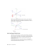
Table Of Contents
- Contents
- Part 1 Tubes and Pipes
- 1 Get Started with Tube & Pipe
- 2 Route Basics
- 3 Set Styles
- 4 Create Rigid Routes and Runs
- Workflow for Rigid Routes
- Create Auto Route Regions
- Manually Create Parametric Regions
- Automatically Dimension Route Sketches
- Create Segments With Precise Values
- Define Parallel and Perpendicular Segments
- Snap Route Points to Existing Geometry
- Place Constraints On Route Sketches
- Create Bends Between Existing Pipe Segments
- Create Pipe Routes With Custom Bends
- Create Bent Tube Routes
- Realign 3D Orthogonal Route Tool
- Control Dimension Visibility
- Populated Routes
- 5 Create and Edit Flexible Hose Routes
- 6 Edit Rigid Routes and Runs
- 7 Use Content Center Libraries
- 8 Author and Publish
- 9 Document Routes and Runs
- Part 2 Cable and Harness
- 10 Get Started with Cable and Harness
- 11 Work With Harness Assemblies
- 12 Use the Cable and Harness Library
- 13 Work with Wires and Cables
- 14 Work with Segments
- 15 Route Wires and Cables
- 16 Work with Splices
- 17 Work with Ribbon Cables
- 18 Generate Reports
- 19 Work With Nailboards and Drawings
- Part 3 IDF Translator
- Index

When you are satisfied with the new position, select a point on the line to
create a segment at the new location. The route path changes to the new
angular position. Using the Rotation Handles, you can also create a series of
bends to achieve a compound bend.
Use Point Snap to Define Points
When the 3D Orthogonal Route tool is active and Point Snap is checked in
the context menu, you can define points by snapping to other model geometry.
Pause your cursor over faces, edges, or work points, a dashed line and preview
point are displayed at the intersection of the line and the plane of the
highlighted edge or face.
The dashed line represents the snap point in relation to the highlighted
geometry. When the preview point is displayed at the needed location, click
the selected geometry and the point is created.
28 | Chapter 2 Route Basics