
2010


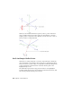
Table Of Contents
- Contents
- Part 1 Tubes and Pipes
- 1 Get Started with Tube & Pipe
- 2 Route Basics
- 3 Set Styles
- 4 Create Rigid Routes and Runs
- Workflow for Rigid Routes
- Create Auto Route Regions
- Manually Create Parametric Regions
- Automatically Dimension Route Sketches
- Create Segments With Precise Values
- Define Parallel and Perpendicular Segments
- Snap Route Points to Existing Geometry
- Place Constraints On Route Sketches
- Create Bends Between Existing Pipe Segments
- Create Pipe Routes With Custom Bends
- Create Bent Tube Routes
- Realign 3D Orthogonal Route Tool
- Control Dimension Visibility
- Populated Routes
- 5 Create and Edit Flexible Hose Routes
- 6 Edit Rigid Routes and Runs
- 7 Use Content Center Libraries
- 8 Author and Publish
- 9 Document Routes and Runs
- Part 2 Cable and Harness
- 10 Get Started with Cable and Harness
- 11 Work With Harness Assemblies
- 12 Use the Cable and Harness Library
- 13 Work with Wires and Cables
- 14 Work with Segments
- 15 Route Wires and Cables
- 16 Work with Splices
- 17 Work with Ribbon Cables
- 18 Generate Reports
- 19 Work With Nailboards and Drawings
- Part 3 IDF Translator
- Index

The route path changes to the new angular position. If you select the wrong
direction, click the single arrow displayed on the selected axis to revert to the
previous angular position.
Define Bent Tubes Angles
When a tubing with bends style is active, the Rotation Handles are displayed
on the 3D Orthogonal Route tool. When they are displayed you can create a
bend at any angle.
To use the Rotation Handles click the arrow pointing in the angular position
you need, and drag to the required position. The tool snaps in regular
increments based on the 3D Angle Snap value. This value is set on the Tools
tab ➤ Options panel ➤ Document Settings ➤ Modeling tab.
Define Bent Tubes Angles | 27