
2010


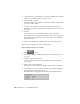


Table Of Contents
- Contents
- Part 1 Tubes and Pipes
- 1 Get Started with Tube & Pipe
- 2 Route Basics
- 3 Set Styles
- 4 Create Rigid Routes and Runs
- Workflow for Rigid Routes
- Create Auto Route Regions
- Manually Create Parametric Regions
- Automatically Dimension Route Sketches
- Create Segments With Precise Values
- Define Parallel and Perpendicular Segments
- Snap Route Points to Existing Geometry
- Place Constraints On Route Sketches
- Create Bends Between Existing Pipe Segments
- Create Pipe Routes With Custom Bends
- Create Bent Tube Routes
- Realign 3D Orthogonal Route Tool
- Control Dimension Visibility
- Populated Routes
- 5 Create and Edit Flexible Hose Routes
- 6 Edit Rigid Routes and Runs
- 7 Use Content Center Libraries
- 8 Author and Publish
- 9 Document Routes and Runs
- Part 2 Cable and Harness
- 10 Get Started with Cable and Harness
- 11 Work With Harness Assemblies
- 12 Use the Cable and Harness Library
- 13 Work with Wires and Cables
- 14 Work with Segments
- 15 Route Wires and Cables
- 16 Work with Splices
- 17 Work with Ribbon Cables
- 18 Generate Reports
- 19 Work With Nailboards and Drawings
- Part 3 IDF Translator
- Index

particular item. To assign a new color, click the arrow beside Item Color
and select from the palette.
11 Click OK.
To exit the dialog box without importing any data, click Cancel.
When the selected data is imported, a standard .iam file with the IDF
board components is created, as shown in the following illustration.
The browser and BOM are updated with the IDF information.
12 Look at the browser to see the results of the import.
When imported as an assembly document, the board components are
translated into multiple parts that are contained in the new assembly.
Each part file contains the data for one or more component instance.
The following illustration shows the results of importing the idf.brd file
in the browser.
374 | Chapter 20 Use the IDF Translator