
2010


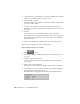


Table Of Contents
- Contents
- Part 1 Tubes and Pipes
- 1 Get Started with Tube & Pipe
- 2 Route Basics
- 3 Set Styles
- 4 Create Rigid Routes and Runs
- Workflow for Rigid Routes
- Create Auto Route Regions
- Manually Create Parametric Regions
- Automatically Dimension Route Sketches
- Create Segments With Precise Values
- Define Parallel and Perpendicular Segments
- Snap Route Points to Existing Geometry
- Place Constraints On Route Sketches
- Create Bends Between Existing Pipe Segments
- Create Pipe Routes With Custom Bends
- Create Bent Tube Routes
- Realign 3D Orthogonal Route Tool
- Control Dimension Visibility
- Populated Routes
- 5 Create and Edit Flexible Hose Routes
- 6 Edit Rigid Routes and Runs
- 7 Use Content Center Libraries
- 8 Author and Publish
- 9 Document Routes and Runs
- Part 2 Cable and Harness
- 10 Get Started with Cable and Harness
- 11 Work With Harness Assemblies
- 12 Use the Cable and Harness Library
- 13 Work with Wires and Cables
- 14 Work with Segments
- 15 Route Wires and Cables
- 16 Work with Splices
- 17 Work with Ribbon Cables
- 18 Generate Reports
- 19 Work With Nailboards and Drawings
- Part 3 IDF Translator
- Index

5 On the Import IDF Options dialog box, view the summary data, and then
select part or assembly as the type of file to create.
6 Select the items to import.
All items are imported by default. Clear the check mark from the items
you do not want to import.
7 To import other outlines, components, or reference designators in a
different color, click the component name, and then select a color from
the palette
8 Click OK.
To exit the dialog box without importing any data, click Cancel.
The assembly or part document for the imported IDF data is displayed,
with the IDF board components. The browser and BOM are populated
with the IDF data.
9 Return to the destination assembly to place the component as usual.
In this exercise, you import a board as a new assembly.
Import an IDF board file as an assembly
1 Click
➤ Open.
2 On the Open dialog box, change the file type to IDF Board File (.brd, .emn,
.bdf, .idb).
3 Navigate to the Autodesk\Inventor
<version>\Samples\Models\Translation\IDFTranslator folder, and then
select idf.brd.
4 Click Open to start reading data.
The status bar is displayed indicating the progress as files are being read.
5 On the Import IDF Options dialog box, review the general information
displayed about the data being imported.
The information is displayed as shown in the following illustration.
372 | Chapter 20 Use the IDF Translator