
2010


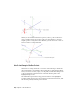
Table Of Contents
- Contents
- Part 1 Tubes and Pipes
- 1 Get Started with Tube & Pipe
- 2 Route Basics
- 3 Set Styles
- 4 Create Rigid Routes and Runs
- Workflow for Rigid Routes
- Create Auto Route Regions
- Manually Create Parametric Regions
- Automatically Dimension Route Sketches
- Create Segments With Precise Values
- Define Parallel and Perpendicular Segments
- Snap Route Points to Existing Geometry
- Place Constraints On Route Sketches
- Create Bends Between Existing Pipe Segments
- Create Pipe Routes With Custom Bends
- Create Bent Tube Routes
- Realign 3D Orthogonal Route Tool
- Control Dimension Visibility
- Populated Routes
- 5 Create and Edit Flexible Hose Routes
- 6 Edit Rigid Routes and Runs
- 7 Use Content Center Libraries
- 8 Author and Publish
- 9 Document Routes and Runs
- Part 2 Cable and Harness
- 10 Get Started with Cable and Harness
- 11 Work With Harness Assemblies
- 12 Use the Cable and Harness Library
- 13 Work with Wires and Cables
- 14 Work with Segments
- 15 Route Wires and Cables
- 16 Work with Splices
- 17 Work with Ribbon Cables
- 18 Generate Reports
- 19 Work With Nailboards and Drawings
- Part 3 IDF Translator
- Index

Change Tool Displays
Both tool color and size can be changed. Tool size is changed using the plus
(+) or minus (-) keys on the keypad. Use plus (+) to increase the size, and minus
(-) to reduce it. To adjust the colors in which the direction axes, line extender,
or tooltip are displayed, set the colors as you would other color format styles.
Set colors in the display of the 3D Orthogonal Route tool
1 Open a tube and pipe assembly file containing at least one route. You
can use the Tube & Pipe sample files, which are installed in
Autodesk\Inventor <version>\Samples\Models\Tube & Pipe by default.
2 Activate the top-level assembly or Tube & Pipe Runs subassembly.
3 On the ribbon, click Manage tab ➤ Styles and Standards panel ➤ Styles
Editor .
4 In the Styles and Standards Editor dialog box, expand Color in the left
pane and select a Route_UI_Tool_(toolname) color style.
5 Set the appropriate color attributes.
6 Click Save to apply color changes immediately. Otherwise, colors become
effective when you click Done to close the dialog box.
Define Angular Position and Rotation Snap
The rotation arrows and direction axes can be displayed when defining routes
and placing fittings, and then again when editing and repositioning routes
Change Tool Displays | 25