
2010


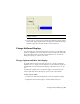


Table Of Contents
- Contents
- Part 1 Tubes and Pipes
- 1 Get Started with Tube & Pipe
- 2 Route Basics
- 3 Set Styles
- 4 Create Rigid Routes and Runs
- Workflow for Rigid Routes
- Create Auto Route Regions
- Manually Create Parametric Regions
- Automatically Dimension Route Sketches
- Create Segments With Precise Values
- Define Parallel and Perpendicular Segments
- Snap Route Points to Existing Geometry
- Place Constraints On Route Sketches
- Create Bends Between Existing Pipe Segments
- Create Pipe Routes With Custom Bends
- Create Bent Tube Routes
- Realign 3D Orthogonal Route Tool
- Control Dimension Visibility
- Populated Routes
- 5 Create and Edit Flexible Hose Routes
- 6 Edit Rigid Routes and Runs
- 7 Use Content Center Libraries
- 8 Author and Publish
- 9 Document Routes and Runs
- Part 2 Cable and Harness
- 10 Get Started with Cable and Harness
- 11 Work With Harness Assemblies
- 12 Use the Cable and Harness Library
- 13 Work with Wires and Cables
- 14 Work with Segments
- 15 Route Wires and Cables
- 16 Work with Splices
- 17 Work with Ribbon Cables
- 18 Generate Reports
- 19 Work With Nailboards and Drawings
- Part 3 IDF Translator
- Index

2 On the ribbon, click Nailboard tab ➤ Manage panel ➤
Property Display.
3 On the Property Display dialog box under Select Filters, click All Pins.
4 In the Property Name list, select Pin Name.
5 Under Display Options, select Value Only, and then click Apply.
6 In the graphics window a rubberband line appears from the property text
box, which is attaches the cursor to the associated object. Click to place
the property as shown.
All properties are automatically placed based on this selection.
7 To place the part properties, select All Parts, select RefDes and Part
Number, select Value Only, and then click Apply.
Use CTRL + click to select multiple items in the list.
8 In the graphics window, click to place the part properties.
356 | Chapter 19 Work With Nailboards and Drawings