
2010


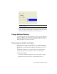


Table Of Contents
- Contents
- Part 1 Tubes and Pipes
- 1 Get Started with Tube & Pipe
- 2 Route Basics
- 3 Set Styles
- 4 Create Rigid Routes and Runs
- Workflow for Rigid Routes
- Create Auto Route Regions
- Manually Create Parametric Regions
- Automatically Dimension Route Sketches
- Create Segments With Precise Values
- Define Parallel and Perpendicular Segments
- Snap Route Points to Existing Geometry
- Place Constraints On Route Sketches
- Create Bends Between Existing Pipe Segments
- Create Pipe Routes With Custom Bends
- Create Bent Tube Routes
- Realign 3D Orthogonal Route Tool
- Control Dimension Visibility
- Populated Routes
- 5 Create and Edit Flexible Hose Routes
- 6 Edit Rigid Routes and Runs
- 7 Use Content Center Libraries
- 8 Author and Publish
- 9 Document Routes and Runs
- Part 2 Cable and Harness
- 10 Get Started with Cable and Harness
- 11 Work With Harness Assemblies
- 12 Use the Cable and Harness Library
- 13 Work with Wires and Cables
- 14 Work with Segments
- 15 Route Wires and Cables
- 16 Work with Splices
- 17 Work with Ribbon Cables
- 18 Generate Reports
- 19 Work With Nailboards and Drawings
- Part 3 IDF Translator
- Index

2 Right-click the segment point or end point of longest wire, and then
select Fan In/Out ➤ Fan Out.
3 In the Fan Out Wires dialog box, click OK.
NOTE Right-click a wire in the fanned out state, and then select Fan Out from the
context menu to change the sorting direction or angle between the outermost
wires.
Arrange the Label
To arrange the label, first set the label to show in the nailboard. Once labels
are set to show, you can manually rearrange individual labels by dragging.
1 In the browser, right-click Harness Assembly 1, and then select Nailboard
Settings.
2 On the Nailboard Settings dialog box under Virtual Parts, click the Show
Labels check box, and then click OK.
3 Click and drag the text box to change its position as shown.
350 | Chapter 19 Work With Nailboards and Drawings