
2010


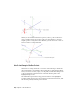
Table Of Contents
- Contents
- Part 1 Tubes and Pipes
- 1 Get Started with Tube & Pipe
- 2 Route Basics
- 3 Set Styles
- 4 Create Rigid Routes and Runs
- Workflow for Rigid Routes
- Create Auto Route Regions
- Manually Create Parametric Regions
- Automatically Dimension Route Sketches
- Create Segments With Precise Values
- Define Parallel and Perpendicular Segments
- Snap Route Points to Existing Geometry
- Place Constraints On Route Sketches
- Create Bends Between Existing Pipe Segments
- Create Pipe Routes With Custom Bends
- Create Bent Tube Routes
- Realign 3D Orthogonal Route Tool
- Control Dimension Visibility
- Populated Routes
- 5 Create and Edit Flexible Hose Routes
- 6 Edit Rigid Routes and Runs
- 7 Use Content Center Libraries
- 8 Author and Publish
- 9 Document Routes and Runs
- Part 2 Cable and Harness
- 10 Get Started with Cable and Harness
- 11 Work With Harness Assemblies
- 12 Use the Cable and Harness Library
- 13 Work with Wires and Cables
- 14 Work with Segments
- 15 Route Wires and Cables
- 16 Work with Splices
- 17 Work with Ribbon Cables
- 18 Generate Reports
- 19 Work With Nailboards and Drawings
- Part 3 IDF Translator
- Index
Hose Route Points
In hose routes, intermediate route points are used to control the shape of the
splines. They are not associated to any fittings. Depending on how the hose
route style defines the start fitting and end fitting, intermediate route points
can be inserted at an appropriate time.
To reposition the hose route points, you can place geometric constraints or
adjust the offset distances from existing geometry using the Redefine tool.
Editing the hose length does not impact the position of the adjacent hose
route points.
3D Orthogonal Route Tool
The 3D Orthogonal Route tool appears as soon as you begin selecting route
points in the graphics window. It contains several elements that guide selection
of valid route points.
When the 3D Orthogonal Route tool first appears, only the line extender is
displayed. With the line extender you can select points that are offset from a
selected edge. Once you select a point along the line, other elements of the
3D Orthogonal Route tool appear at the selected point.
The elements displayed are dependent on what is selected, the connection
geometry, and set styles. For example, the 3D Orthogonal Route tool includes
different elements depending on whether you are creating a pipe route with
fittings or a tube route with bends. Some elements are common to both styles.
Valid points, those that will make a connection of the allowable length, are
highlighted with a green dot as you move the cursor over the lines in the tool.
Points that do not fall within the range set by the style criteria are displayed
as a yellow x. The size of the tool can be increased if the line is not long
enough.
Tool Elements for Pipe Routing
When a rigid piping style is active and all elements are displayed on the 3D
Orthogonal Route tool, you can:
■ Rotate freely around the local axis.
■ Change direction in 90- or 45-degree increments.
■ Create points from referenced geometry.
Hose Route Points | 23