
2010


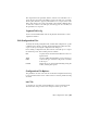


Table Of Contents
- Contents
- Part 1 Tubes and Pipes
- 1 Get Started with Tube & Pipe
- 2 Route Basics
- 3 Set Styles
- 4 Create Rigid Routes and Runs
- Workflow for Rigid Routes
- Create Auto Route Regions
- Manually Create Parametric Regions
- Automatically Dimension Route Sketches
- Create Segments With Precise Values
- Define Parallel and Perpendicular Segments
- Snap Route Points to Existing Geometry
- Place Constraints On Route Sketches
- Create Bends Between Existing Pipe Segments
- Create Pipe Routes With Custom Bends
- Create Bent Tube Routes
- Realign 3D Orthogonal Route Tool
- Control Dimension Visibility
- Populated Routes
- 5 Create and Edit Flexible Hose Routes
- 6 Edit Rigid Routes and Runs
- 7 Use Content Center Libraries
- 8 Author and Publish
- 9 Document Routes and Runs
- Part 2 Cable and Harness
- 10 Get Started with Cable and Harness
- 11 Work With Harness Assemblies
- 12 Use the Cable and Harness Library
- 13 Work with Wires and Cables
- 14 Work with Segments
- 15 Route Wires and Cables
- 16 Work with Splices
- 17 Work with Ribbon Cables
- 18 Generate Reports
- 19 Work With Nailboards and Drawings
- Part 3 IDF Translator
- Index

information such as the name of the project or model used, and a date can
also be included. Use the scroll bar to view all the information, if necessary.
Table Tab
On the table tab, set the columns and properties to use for parsing the report.
Click the buttons to add and remove columns, and click the input boxes to
add property values to each field. If an arrow is displayed, click the arrow to
select from a list.
Keywords are used to perform certain functions, such as counting the number
of like objects based on a specified property name.
See the Help for details about key words.
In the Table tab on the Edit Configuration dialog box, link types are used to
obtain information on an object type, such as a pin or part, when running a
report on a different object type, such as a wire. The following table shows
the link types you can use for the different harness component object types.
SplicesCable
Wire
PartPinWireSegmentLink Types
XXXXXXNone
XGETPART
XXGETPART1, GETPART2
XXGETSEGMENTS
XGETWIRES
XXGETPINS
XXGETPIN1,GETPIN2
XXGETPINSGETWIRES
XXGETPINSGETWIRESGETPIN2
XXGETPINSGETWIRESGETPART2
The rows of the table are defined as follows:
334 | Chapter 18 Generate Reports