
2010
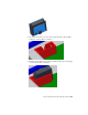


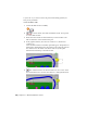


Table Of Contents
- Contents
- Part 1 Tubes and Pipes
- 1 Get Started with Tube & Pipe
- 2 Route Basics
- 3 Set Styles
- 4 Create Rigid Routes and Runs
- Workflow for Rigid Routes
- Create Auto Route Regions
- Manually Create Parametric Regions
- Automatically Dimension Route Sketches
- Create Segments With Precise Values
- Define Parallel and Perpendicular Segments
- Snap Route Points to Existing Geometry
- Place Constraints On Route Sketches
- Create Bends Between Existing Pipe Segments
- Create Pipe Routes With Custom Bends
- Create Bent Tube Routes
- Realign 3D Orthogonal Route Tool
- Control Dimension Visibility
- Populated Routes
- 5 Create and Edit Flexible Hose Routes
- 6 Edit Rigid Routes and Runs
- 7 Use Content Center Libraries
- 8 Author and Publish
- 9 Document Routes and Runs
- Part 2 Cable and Harness
- 10 Get Started with Cable and Harness
- 11 Work With Harness Assemblies
- 12 Use the Cable and Harness Library
- 13 Work with Wires and Cables
- 14 Work with Segments
- 15 Route Wires and Cables
- 16 Work with Splices
- 17 Work with Ribbon Cables
- 18 Generate Reports
- 19 Work With Nailboards and Drawings
- Part 3 IDF Translator
- Index

This action aligns the shaft perpendicular to the selected face. To align
the shaft parallel to existing geometry, select an edge.
3 Click OK and the fold is created with the specified direction and
alignment.
NOTE Like editing other harness objects, you can right-click ribbon cable
work points and use Redefine Point and 3D Move/Rotate to move route
points. Ribbon cable work points cannot be rotated. For folds, only the work
point used to create the fold can be manipulated.
4 In the browser, expand the Ribbon Cables folder and the ribbon cable.
You should see Ribbon1, Fold1, and Ribbon2.
Adjust twist
The ribbon cable body aligns parallel to the slot in the D-Sub Ribbon Cable
connector. To adjust the ribbon cable at a selected point, use Twist Control.
Adjust Ribbon Cable Orientation and Shape | 325