
2010


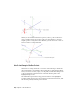
Table Of Contents
- Contents
- Part 1 Tubes and Pipes
- 1 Get Started with Tube & Pipe
- 2 Route Basics
- 3 Set Styles
- 4 Create Rigid Routes and Runs
- Workflow for Rigid Routes
- Create Auto Route Regions
- Manually Create Parametric Regions
- Automatically Dimension Route Sketches
- Create Segments With Precise Values
- Define Parallel and Perpendicular Segments
- Snap Route Points to Existing Geometry
- Place Constraints On Route Sketches
- Create Bends Between Existing Pipe Segments
- Create Pipe Routes With Custom Bends
- Create Bent Tube Routes
- Realign 3D Orthogonal Route Tool
- Control Dimension Visibility
- Populated Routes
- 5 Create and Edit Flexible Hose Routes
- 6 Edit Rigid Routes and Runs
- 7 Use Content Center Libraries
- 8 Author and Publish
- 9 Document Routes and Runs
- Part 2 Cable and Harness
- 10 Get Started with Cable and Harness
- 11 Work With Harness Assemblies
- 12 Use the Cable and Harness Library
- 13 Work with Wires and Cables
- 14 Work with Segments
- 15 Route Wires and Cables
- 16 Work with Splices
- 17 Work with Ribbon Cables
- 18 Generate Reports
- 19 Work With Nailboards and Drawings
- Part 3 IDF Translator
- Index

Solutions are evaluated and prioritized based on length and number of
segments. The length and segment information is included in a tooltip as you
consider the available solutions.
If you must switch to a new auto region solution in later edits, activate the
route environment. The Alternate Auto Solution tool is available when
right-clicking the auto region in the Model browser.
Parametric Regions
Along with the 3D Orthogonal Route tool, you can use geometric constraints,
dimensions, custom bends, point snap, and rotation snap to manually define
sketched route points.
If existing geometry such as a vertex, linear geometry, planar faces, and work
features (including work points, work axes, and work planes) can help navigate
through the route system, include them as reference geometry. You can then
apply appropriate geometric constraints and dimension constraints to define
the design.
In addition, you can draw construction lines from sketched route points and
then use the General Dimension tool to position the coplanar segment
accurately.
NOTE It is best to plan for route constraints before starting the design.
About Flexible Hose Routes
Flexible hose routes can contain up to three parts: a start fitting, a hose
segment, and an end fitting. The start fitting and end fitting for a flexible hose
must have two connection points. Flexible hose routes can also consist of only
the hose, with both fittings suppressed, or a hose with one fitting suppressed.
To provide more control over hose shape, you can insert intermediate route
points in the hose route as you create it. As you make your selections, a preview
line appears between the selected points to help you visualize the route.
Flexible hose routes can be created between standard assembly geometry or
initiated from fittings dropped onto existing routes to create a branch.
Parametric Regions | 21