
2010


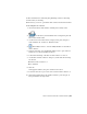

Table Of Contents
- Contents
- Part 1 Tubes and Pipes
- 1 Get Started with Tube & Pipe
- 2 Route Basics
- 3 Set Styles
- 4 Create Rigid Routes and Runs
- Workflow for Rigid Routes
- Create Auto Route Regions
- Manually Create Parametric Regions
- Automatically Dimension Route Sketches
- Create Segments With Precise Values
- Define Parallel and Perpendicular Segments
- Snap Route Points to Existing Geometry
- Place Constraints On Route Sketches
- Create Bends Between Existing Pipe Segments
- Create Pipe Routes With Custom Bends
- Create Bent Tube Routes
- Realign 3D Orthogonal Route Tool
- Control Dimension Visibility
- Populated Routes
- 5 Create and Edit Flexible Hose Routes
- 6 Edit Rigid Routes and Runs
- 7 Use Content Center Libraries
- 8 Author and Publish
- 9 Document Routes and Runs
- Part 2 Cable and Harness
- 10 Get Started with Cable and Harness
- 11 Work With Harness Assemblies
- 12 Use the Cable and Harness Library
- 13 Work with Wires and Cables
- 14 Work with Segments
- 15 Route Wires and Cables
- 16 Work with Splices
- 17 Work with Ribbon Cables
- 18 Generate Reports
- 19 Work With Nailboards and Drawings
- Part 3 IDF Translator
- Index

For more information on authoring and publishing connectors and using
Content Center, see the Help.
In this exercise, you use a 10-pin ribbon cable connector from Content Center.
Locate and place the connector
1 Activate the Ribbon Cable harness assembly, if not already active.
2
On the ribbon, click Assemble tab ➤ Component panel ➤
Place from Content Center .
3 On the Place from Content Center, Category View pane, navigate to
Cable & Harness ➤ Connectors ➤ Ribbon Cable.
4
Click Family Preview to view the family members for the ribbon
cable connector.
5 In the preview table, note the Member name for the 10-pin connector.
In this case, it is the first member in the list.
6 Double-click the image of the ribbon cable connector to select it.
7 On the Ribbon Cable Connector dialog box, ensure that the following
are selected:
■ Ribbon Cable Connector-01
■ As Standard
8 Click OK.
In the graphics window, the part is attached to the cursor.
9 Rotate the enclosure to get a better view of the RC Male Connector (1).
10 Click in the background of the graphics window to place the part (2).
Exact placement is not important.
Place Connectors from Content Center | 317