
2010

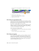


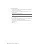


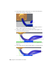
Table Of Contents
- Contents
- Part 1 Tubes and Pipes
- 1 Get Started with Tube & Pipe
- 2 Route Basics
- 3 Set Styles
- 4 Create Rigid Routes and Runs
- Workflow for Rigid Routes
- Create Auto Route Regions
- Manually Create Parametric Regions
- Automatically Dimension Route Sketches
- Create Segments With Precise Values
- Define Parallel and Perpendicular Segments
- Snap Route Points to Existing Geometry
- Place Constraints On Route Sketches
- Create Bends Between Existing Pipe Segments
- Create Pipe Routes With Custom Bends
- Create Bent Tube Routes
- Realign 3D Orthogonal Route Tool
- Control Dimension Visibility
- Populated Routes
- 5 Create and Edit Flexible Hose Routes
- 6 Edit Rigid Routes and Runs
- 7 Use Content Center Libraries
- 8 Author and Publish
- 9 Document Routes and Runs
- Part 2 Cable and Harness
- 10 Get Started with Cable and Harness
- 11 Work With Harness Assemblies
- 12 Use the Cable and Harness Library
- 13 Work with Wires and Cables
- 14 Work with Segments
- 15 Route Wires and Cables
- 16 Work with Splices
- 17 Work with Ribbon Cables
- 18 Generate Reports
- 19 Work With Nailboards and Drawings
- Part 3 IDF Translator
- Index

The segments are updated accordingly.
Change Displays of Segments
Segments can be displayed as rendered or centerlines. Rendered display
provides a three-dimensional appearance, while centerline display provides
an unobstructed view of the work points and path.
Like wires, the display options can be set for individual segments or for all
segments in a selected harness assembly. The display preference can be set in
different ways, either with the context menu for the segment occurrence or
the Segments folder, the Segment Properties dialog box, or the Display Settings
tool on the Cable and Harness tab. The occurrence level display settings always
override the current display state.
Change the display for a selected segment
1 Double-click Harness Assembly1 if it is not already active.
2 In the browser or graphics window, right-click a segment and select
Harness Properties.
3
On the Segment Properties dialog box, Display tab, click the tool
for the Centerline display option.
4 To change the display setting for all segments, select the Segments folder
in the browser, right-click, and select Display All As Rendered from the
context menu.
You can also change the display of a single segment by selecting the
Display As Rendered option from the Display Settings tool on the Visibility
panel of the Cable and Harness tab or by right-clicking a segment and
selecting Display As Rendered from the context menu.
Set Segment Defaults
Several default settings are available for harness segments. With Harness
Assembly1 still active, do the following:
Change Displays of Segments | 293