
2010


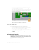


Table Of Contents
- Contents
- Part 1 Tubes and Pipes
- 1 Get Started with Tube & Pipe
- 2 Route Basics
- 3 Set Styles
- 4 Create Rigid Routes and Runs
- Workflow for Rigid Routes
- Create Auto Route Regions
- Manually Create Parametric Regions
- Automatically Dimension Route Sketches
- Create Segments With Precise Values
- Define Parallel and Perpendicular Segments
- Snap Route Points to Existing Geometry
- Place Constraints On Route Sketches
- Create Bends Between Existing Pipe Segments
- Create Pipe Routes With Custom Bends
- Create Bent Tube Routes
- Realign 3D Orthogonal Route Tool
- Control Dimension Visibility
- Populated Routes
- 5 Create and Edit Flexible Hose Routes
- 6 Edit Rigid Routes and Runs
- 7 Use Content Center Libraries
- 8 Author and Publish
- 9 Document Routes and Runs
- Part 2 Cable and Harness
- 10 Get Started with Cable and Harness
- 11 Work With Harness Assemblies
- 12 Use the Cable and Harness Library
- 13 Work with Wires and Cables
- 14 Work with Segments
- 15 Route Wires and Cables
- 16 Work with Splices
- 17 Work with Ribbon Cables
- 18 Generate Reports
- 19 Work With Nailboards and Drawings
- Part 3 IDF Translator
- Index
Restore Library-Level Properties
To restore a property value to its original library-level value, position the cursor
anywhere in the selected table row, right-click, and then select Restore.
In this exercise, you restore the library-level property value for the custom
Volt property with the value override.
Restore a library-level property value
1 With the Wire Properties dialog box still open, click the Volt row in the
custom property table to select it.
Notice that the library-level property name, and value appear in the
bottom left of the dialog box.
2 Right-click anywhere in the row, and then select Restore on the context
menu.
The wire library replaces the occurrence value with the library value.
3 Click OK.
Change Wire and Cable Displays
Wires and cables can be displayed as either rendered or centerline. Centerline
display is the default and should be used for optimal performance while
creating and routing wires and cables.
If Rendered Display is selected, the harness object is drawn as a
three-dimensional shaded solid with the diameter as set in the library
definition, which is similar to the physical object appears. With centerline
display the objects are drawn as lines, making it easier to see and work on
existing model geometry.
Restore Library-Level Properties | 277