
2010


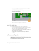


Table Of Contents
- Contents
- Part 1 Tubes and Pipes
- 1 Get Started with Tube & Pipe
- 2 Route Basics
- 3 Set Styles
- 4 Create Rigid Routes and Runs
- Workflow for Rigid Routes
- Create Auto Route Regions
- Manually Create Parametric Regions
- Automatically Dimension Route Sketches
- Create Segments With Precise Values
- Define Parallel and Perpendicular Segments
- Snap Route Points to Existing Geometry
- Place Constraints On Route Sketches
- Create Bends Between Existing Pipe Segments
- Create Pipe Routes With Custom Bends
- Create Bent Tube Routes
- Realign 3D Orthogonal Route Tool
- Control Dimension Visibility
- Populated Routes
- 5 Create and Edit Flexible Hose Routes
- 6 Edit Rigid Routes and Runs
- 7 Use Content Center Libraries
- 8 Author and Publish
- 9 Document Routes and Runs
- Part 2 Cable and Harness
- 10 Get Started with Cable and Harness
- 11 Work With Harness Assemblies
- 12 Use the Cable and Harness Library
- 13 Work with Wires and Cables
- 14 Work with Segments
- 15 Route Wires and Cables
- 16 Work with Splices
- 17 Work with Ribbon Cables
- 18 Generate Reports
- 19 Work With Nailboards and Drawings
- Part 3 IDF Translator
- Index

Redefine and Move Wire Points
Once the points are added you can redefine the points to an arbitrary location
or feature to achieve the shape you need. Wire points based on an arbitrary
point on a face are offset a specified distance and does not update to changes
in the model, including changes from positional representations. Like the
points used to define pins on parts, points based on existing geometry are not
offset and update to changes in the model.
You can also reposition wire work points dynamically or by precise coordinates
with the 3D Move/Rotate tool.
Manipulate wire points
1 In the browser, expand wire 2207, right-click the second work point you
created and then select Redefine Point from the context menu.
2 In the graphics window, pause the cursor near the tab on the enclosure
as shown. Notice the tooltip that shows the offset value for the point.
3 In the graphics window, right-click (not on the point), select Edit Offset
from the context menu, and then enter .200 to change the offset.
4 Click the point in the location shown to create a point that is offset from
the face of the enclosure. The wire recomputes.
NOTE To create a point that would update to changes in the model, click
the circular edge of the tab.
5 If appropriate, rotate the view to see the increased offset.
Redefine and Move Wire Points | 273