
2010


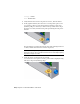


Table Of Contents
- Contents
- Part 1 Tubes and Pipes
- 1 Get Started with Tube & Pipe
- 2 Route Basics
- 3 Set Styles
- 4 Create Rigid Routes and Runs
- Workflow for Rigid Routes
- Create Auto Route Regions
- Manually Create Parametric Regions
- Automatically Dimension Route Sketches
- Create Segments With Precise Values
- Define Parallel and Perpendicular Segments
- Snap Route Points to Existing Geometry
- Place Constraints On Route Sketches
- Create Bends Between Existing Pipe Segments
- Create Pipe Routes With Custom Bends
- Create Bent Tube Routes
- Realign 3D Orthogonal Route Tool
- Control Dimension Visibility
- Populated Routes
- 5 Create and Edit Flexible Hose Routes
- 6 Edit Rigid Routes and Runs
- 7 Use Content Center Libraries
- 8 Author and Publish
- 9 Document Routes and Runs
- Part 2 Cable and Harness
- 10 Get Started with Cable and Harness
- 11 Work With Harness Assemblies
- 12 Use the Cable and Harness Library
- 13 Work with Wires and Cables
- 14 Work with Segments
- 15 Route Wires and Cables
- 16 Work with Splices
- 17 Work with Ribbon Cables
- 18 Generate Reports
- 19 Work With Nailboards and Drawings
- Part 3 IDF Translator
- Index

8 When the tooltip is displayed as J12 Pin 1, click the point to select the
second pin.
9 To create the wire, click Apply on the dialog box.
The wire is created as centerline or rendered, depending on the display
setting. Display is set to centerline for wires and cables by default.
10 While the dialog box is still open, click the Properties button to view the
properties for the library wire. Click OK.
The wire that is placed is an occurrence wire. The occurrence inherits the
properties from the library wire.
11 On the Create Wire dialog box, click Cancel.
12
Before adding the second wire, use the skills you learned
previously to change the natural curvature setting for wires and cables
back to With Natural Curvature .
13 For the wires to display natural curvature, the associated connectors must
be authored
Double-click 360124:1.
14 Click Manage tab ➤ Author panel ➤ Connector.
15 Click on the top face of 360124:1to define the outward normal direction.
16 Click OK to author the connector.
17 Click OK to close the message box. Return to the harness assembly.
18 You need to author the other connectors to display natural curvature.
Follow the steps to author connectors for LTP and 360575.
Insert Wires Manually | 255