
2010
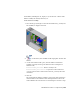


Table Of Contents
- Contents
- Part 1 Tubes and Pipes
- 1 Get Started with Tube & Pipe
- 2 Route Basics
- 3 Set Styles
- 4 Create Rigid Routes and Runs
- Workflow for Rigid Routes
- Create Auto Route Regions
- Manually Create Parametric Regions
- Automatically Dimension Route Sketches
- Create Segments With Precise Values
- Define Parallel and Perpendicular Segments
- Snap Route Points to Existing Geometry
- Place Constraints On Route Sketches
- Create Bends Between Existing Pipe Segments
- Create Pipe Routes With Custom Bends
- Create Bent Tube Routes
- Realign 3D Orthogonal Route Tool
- Control Dimension Visibility
- Populated Routes
- 5 Create and Edit Flexible Hose Routes
- 6 Edit Rigid Routes and Runs
- 7 Use Content Center Libraries
- 8 Author and Publish
- 9 Document Routes and Runs
- Part 2 Cable and Harness
- 10 Get Started with Cable and Harness
- 11 Work With Harness Assemblies
- 12 Use the Cable and Harness Library
- 13 Work with Wires and Cables
- 14 Work with Segments
- 15 Route Wires and Cables
- 16 Work with Splices
- 17 Work with Ribbon Cables
- 18 Generate Reports
- 19 Work With Nailboards and Drawings
- Part 3 IDF Translator
- Index

Use the Cable and Harness Browser
All harness objects added to an assembly file are automatically contained in
the harness assembly. The objects include wires, cables, cable wires, ribbon
cables, segments, splices, virtual parts, and optionally electrical parts and pins.
Each harness assembly contains an Origin and a Representations folder and
a single harness part. Although harness assemblies respond to representations
in the parent assembly, they do not respond as expected to representations
created at the harness assembly. For best results, create representations at the
parent assembly level only.
The harness part contains one folder for each of the harness objects that make
up the harness. Each segment has a work point for every point used to shape
the segment. Ribbon cables contain work points and folds used to shape the
ribbon cable. The Virtual Parts folder contains a folder for each type of virtual
part in the harness.
NOTE Promoting a harness part from its parent assembly corrupts the cable and
harness data. In this case, close the assembly without saving. Demoting the harness
back to the subassembly does not fix the data.
Set Properties for Harness Components
Every harness component contains a set of properties. These properties are
used for the documentation you produce, such as reports and drawings.
Properties are also used to check specific aspects of the design, such as bend
radius and bundle diameters.
Properties are added at different levels within the assembly. They can be added
to the source component in the library as well as to any occurrences of that
component within the assembly.
When you create a harness object, some properties are required, such as the
Pin Name for an electrical part occurrence, or the Wire ID for a wire. You can
decide on which other properties to set.
The documentation you produce for downstream consumers drives the
properties you set. Some properties, such as length or adjusted length for a
harness segment are derived from the placement or settings of the related
component. These properties cannot be changed, but can be viewed and used
in the documentation.
You can set and view properties when the component is active in Cable and
Harness. Some properties can also be accessed from other objects. For example,
Use the Cable and Harness Browser | 231