
2010
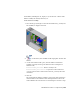


Table Of Contents
- Contents
- Part 1 Tubes and Pipes
- 1 Get Started with Tube & Pipe
- 2 Route Basics
- 3 Set Styles
- 4 Create Rigid Routes and Runs
- Workflow for Rigid Routes
- Create Auto Route Regions
- Manually Create Parametric Regions
- Automatically Dimension Route Sketches
- Create Segments With Precise Values
- Define Parallel and Perpendicular Segments
- Snap Route Points to Existing Geometry
- Place Constraints On Route Sketches
- Create Bends Between Existing Pipe Segments
- Create Pipe Routes With Custom Bends
- Create Bent Tube Routes
- Realign 3D Orthogonal Route Tool
- Control Dimension Visibility
- Populated Routes
- 5 Create and Edit Flexible Hose Routes
- 6 Edit Rigid Routes and Runs
- 7 Use Content Center Libraries
- 8 Author and Publish
- 9 Document Routes and Runs
- Part 2 Cable and Harness
- 10 Get Started with Cable and Harness
- 11 Work With Harness Assemblies
- 12 Use the Cable and Harness Library
- 13 Work with Wires and Cables
- 14 Work with Segments
- 15 Route Wires and Cables
- 16 Work with Splices
- 17 Work with Ribbon Cables
- 18 Generate Reports
- 19 Work With Nailboards and Drawings
- Part 3 IDF Translator
- Index

5 Locate the new harness assembly in the browser hierarchy.
NOTE Clicking the Create Harness tool again adds a second harness assembly
after the existing one at the same level.
6 Examine the Visibility panel of the Cable and Harness tab to see the
display settings for wires, cables, ribbon cables, and segments. Click the
arrow to display the list.
The display for these harness objects can be changed at any time. The
display for all objects of a selected type in a selected harness assembly
can also be changed.
7 Activate the top-level assembly and click ➤ Save.
8 Click OK.
The harness assembly is saved using the name and location indicated
previously.
230 | Chapter 11 Work With Harness Assemblies