
2010
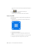


Table Of Contents
- Contents
- Part 1 Tubes and Pipes
- 1 Get Started with Tube & Pipe
- 2 Route Basics
- 3 Set Styles
- 4 Create Rigid Routes and Runs
- Workflow for Rigid Routes
- Create Auto Route Regions
- Manually Create Parametric Regions
- Automatically Dimension Route Sketches
- Create Segments With Precise Values
- Define Parallel and Perpendicular Segments
- Snap Route Points to Existing Geometry
- Place Constraints On Route Sketches
- Create Bends Between Existing Pipe Segments
- Create Pipe Routes With Custom Bends
- Create Bent Tube Routes
- Realign 3D Orthogonal Route Tool
- Control Dimension Visibility
- Populated Routes
- 5 Create and Edit Flexible Hose Routes
- 6 Edit Rigid Routes and Runs
- 7 Use Content Center Libraries
- 8 Author and Publish
- 9 Document Routes and Runs
- Part 2 Cable and Harness
- 10 Get Started with Cable and Harness
- 11 Work With Harness Assemblies
- 12 Use the Cable and Harness Library
- 13 Work with Wires and Cables
- 14 Work with Segments
- 15 Route Wires and Cables
- 16 Work with Splices
- 17 Work with Ribbon Cables
- 18 Generate Reports
- 19 Work With Nailboards and Drawings
- Part 3 IDF Translator
- Index

5 Create the harness assembly.
6 Insert wires, cables, and ribbon cables into the harness assembly, and
then add properties as needed.
7 Create segments that define the possible wire and cable paths through
the assembly.
8 Add properties to the segments as needed.
9 Route wires and cables through selected segments.
10 Insert splices, add wire and cable points, add ribbon cable points and
folds, adjust ribbon cable twist, attach virtual parts, and make other
modifications to the harness.
11 Create a nailboard of the harness assembly and generate parts list and
bill of materials information.
To create the Harness assembly, click Assemble tab ➤ Begin panel ➤ Cable
and Harness.
Create Harness command
In the Create Harness dialog box, provide a unique name and location for the
harness subassembly. By default, the file is named <top level
assembly>.Harness<number>.iam (where number is a sequential number that
increments with each harness assembly) and is saved to the location of the
open assembly file, along with the corresponding harness part. You can provide
a different name and location if appropriate. You can also change the name
to something harness specific or descriptive.
Once you provide the name and location, the system adds a harness assembly
to the browser. It is added to the browser along with other placed components
and is arranged in the order it is added to the assembly. You can locate the
harness anywhere in the assembly hierarchy, except in another harness
assembly. For example, you can nest the harness assembly in another standard
Autodesk Inventor assembly, but not in another harness assembly. When you
edit a harness assembly, you can connect only to harness objects that share
the same parent assembly as that harness assembly.
In this exercise, you open an existing assembly and prepare to wire it. You
also become familiar with the features included in the cable and harness design
228 | Chapter 11 Work With Harness Assemblies