
2010
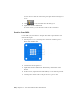
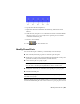


Table Of Contents
- Contents
- Part 1 Tubes and Pipes
- 1 Get Started with Tube & Pipe
- 2 Route Basics
- 3 Set Styles
- 4 Create Rigid Routes and Runs
- Workflow for Rigid Routes
- Create Auto Route Regions
- Manually Create Parametric Regions
- Automatically Dimension Route Sketches
- Create Segments With Precise Values
- Define Parallel and Perpendicular Segments
- Snap Route Points to Existing Geometry
- Place Constraints On Route Sketches
- Create Bends Between Existing Pipe Segments
- Create Pipe Routes With Custom Bends
- Create Bent Tube Routes
- Realign 3D Orthogonal Route Tool
- Control Dimension Visibility
- Populated Routes
- 5 Create and Edit Flexible Hose Routes
- 6 Edit Rigid Routes and Runs
- 7 Use Content Center Libraries
- 8 Author and Publish
- 9 Document Routes and Runs
- Part 2 Cable and Harness
- 10 Get Started with Cable and Harness
- 11 Work With Harness Assemblies
- 12 Use the Cable and Harness Library
- 13 Work with Wires and Cables
- 14 Work with Segments
- 15 Route Wires and Cables
- 16 Work with Splices
- 17 Work with Ribbon Cables
- 18 Generate Reports
- 19 Work With Nailboards and Drawings
- Part 3 IDF Translator
- Index

■ Route wires and cables through harness segments and automatically
calculate lengths and bundle diameters.
■ Configure and generate reports of the harness assembly.
■ Insert and arrange splices, attach virtual parts, and make other
modifications to the harness design.
■ Create accurate 2D harness documentation with intelligent properties and
dimensions that automatically update as the 3D design changes.
■ Use the browser to organize and edit electrical parts, pins, wires, cables,
ribbon cables, splices, virtual parts, and segments. You can also change
visibility on all harness objects through the browser, except for virtual
parts.
■ Optionally, copy and reuse the completed harness in another location.
WARNING Do not perform operations specific to Autodesk Inventor
®
on segments,
wires, cables, and ribbon cables. It can cause problems with operations in cable
and harness. For example, do not use Autodesk Inventor operations such as
extrusions, sweeps, and so on, to change harness objects.
Cable and Harness Environment
To access the Cable and Harness environment, you create or edit a harness
assembly. Features specific to Cable and Harness are available only in this
environment. Other features, such as a Nailboard, are only available once a
valid harness assembly is created.
Some of the features specific to the Cable and Harness environment include:
Panels and commands for the cable and harness envir-
onment.
Cable and Harness
tab
Contained in the Model browser, the Cable and Har-
ness browser items include the contents of one or more
Cable and Harness
browser items
harness assemblies in a hierarchy. The harness assem-
blies act as containers for all the objects created or
placed in that particular harness.
Switches between rendered and centerline display for
wires, segments, and ribbon cables.
Segment, wire, rib-
bon cable display
tools
226 | Chapter 11 Work With Harness Assemblies