
2010


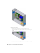


Table Of Contents
- Contents
- Part 1 Tubes and Pipes
- 1 Get Started with Tube & Pipe
- 2 Route Basics
- 3 Set Styles
- 4 Create Rigid Routes and Runs
- Workflow for Rigid Routes
- Create Auto Route Regions
- Manually Create Parametric Regions
- Automatically Dimension Route Sketches
- Create Segments With Precise Values
- Define Parallel and Perpendicular Segments
- Snap Route Points to Existing Geometry
- Place Constraints On Route Sketches
- Create Bends Between Existing Pipe Segments
- Create Pipe Routes With Custom Bends
- Create Bent Tube Routes
- Realign 3D Orthogonal Route Tool
- Control Dimension Visibility
- Populated Routes
- 5 Create and Edit Flexible Hose Routes
- 6 Edit Rigid Routes and Runs
- 7 Use Content Center Libraries
- 8 Author and Publish
- 9 Document Routes and Runs
- Part 2 Cable and Harness
- 10 Get Started with Cable and Harness
- 11 Work With Harness Assemblies
- 12 Use the Cable and Harness Library
- 13 Work with Wires and Cables
- 14 Work with Segments
- 15 Route Wires and Cables
- 16 Work with Splices
- 17 Work with Ribbon Cables
- 18 Generate Reports
- 19 Work With Nailboards and Drawings
- Part 3 IDF Translator
- Index
About Electrical Parts
Electrical parts are normal Autodesk Inventor parts or iParts with extended
properties and one or more defined connection points, known as pins.
Electrical parts are the only harness components that are not created in the
context of a harness assembly. Instead, electrical parts are created by editing
normal Autodesk Inventor parts. While editing the parts you identify the
special work points called pins, provide required properties, and optionally
add additional custom properties. You can define and edit the pins individually
or as a group. Once defined, the electrical part is placed in an assembly.
The part used can be fully modeled or a simple representation of the part, as
long as there is some geometry to designate the connection points, or pins.
For example, the part could be a simple plane with work points representing
the pins. For a group of pins, the part could be a simple plane with a single
point representing the start location for the group. These pins are the attach
points for the wires in the harness assembly.
You can also create, author, and publish your own connectors or place generic
connectors from the Cable and Harness ➤ Connectors category of the Content
Center.
Workflow for Electrical Parts
The harness workflow begins with electrical parts. The following are the basic
steps to create an electrical part and place it in an assembly.
Create an electrical part and place it in an assembly
1 Edit an Autodesk Inventor part.
2 Add individual or group pin definitions, each with a unique name and
additional properties, if appropriate.
3 Optionally, author and publish the connector part to Content Center.
4 Optionally, provide a placeholder reference designator (RefDes) or generic
value for that electrical part type in the part file.
Do it once for each electrical part.
5 Place the part in an assembly.
6 Assign the reference designator for an individual occurrence or group.
The reference designator for the individual occurrence or group is required
About Electrical Parts | 213