
2010
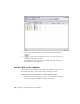


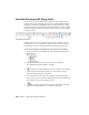

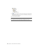


Table Of Contents
- Contents
- Part 1 Tubes and Pipes
- 1 Get Started with Tube & Pipe
- 2 Route Basics
- 3 Set Styles
- 4 Create Rigid Routes and Runs
- Workflow for Rigid Routes
- Create Auto Route Regions
- Manually Create Parametric Regions
- Automatically Dimension Route Sketches
- Create Segments With Precise Values
- Define Parallel and Perpendicular Segments
- Snap Route Points to Existing Geometry
- Place Constraints On Route Sketches
- Create Bends Between Existing Pipe Segments
- Create Pipe Routes With Custom Bends
- Create Bent Tube Routes
- Realign 3D Orthogonal Route Tool
- Control Dimension Visibility
- Populated Routes
- 5 Create and Edit Flexible Hose Routes
- 6 Edit Rigid Routes and Runs
- 7 Use Content Center Libraries
- 8 Author and Publish
- 9 Document Routes and Runs
- Part 2 Cable and Harness
- 10 Get Started with Cable and Harness
- 11 Work With Harness Assemblies
- 12 Use the Cable and Harness Library
- 13 Work with Wires and Cables
- 14 Work with Segments
- 15 Route Wires and Cables
- 16 Work with Splices
- 17 Work with Ribbon Cables
- 18 Generate Reports
- 19 Work With Nailboards and Drawings
- Part 3 IDF Translator
- Index

Annotate Drawings with Piping Styles
You may want to use information that is defined in tube and pipe styles to
annotate tube and pipe drawings. You can start to define sketched symbols,
and then use the Text tool (highlighted below) on the Sketch tab to insert
property references in text. When property values change, text that contains
the property updates with the new values. Pause the cursor over the images
to view the tooltip.
Drawing Sketch panel bar
In this exercise, you create a parts list for the base view (VIEW1), use the
Column Chooser tool to add the Base QTY property to the parts lists. The
Stock Number property is already included in the default parts list style.
Create sketched symbols with piping style data and annotate drawings
1 In the AirSystemAssy.idw drawing window, expand Drawing Resources.
2 Right-click Sketched Symbols and select Define New Symbol.
The drawing sketch environment is activated.
3
On the ribbon, click Sketch tab ➤ Draw panel ➤ Text, and then
click a location in the graphics window to place the first property.
The Format Text dialog box is displayed.
4 Use the default text style and select _Piping Style from the Type list.
The Property option is activated. All piping style properties available in
the Property list are from tube and pipe styles.
5
Select a specific piping style property from the Property list and
click the Add Text Parameter tool, for instance, Standard.
204 | Chapter 9 Document Routes and Runs