
2010
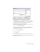


Table Of Contents
- Contents
- Part 1 Tubes and Pipes
- 1 Get Started with Tube & Pipe
- 2 Route Basics
- 3 Set Styles
- 4 Create Rigid Routes and Runs
- Workflow for Rigid Routes
- Create Auto Route Regions
- Manually Create Parametric Regions
- Automatically Dimension Route Sketches
- Create Segments With Precise Values
- Define Parallel and Perpendicular Segments
- Snap Route Points to Existing Geometry
- Place Constraints On Route Sketches
- Create Bends Between Existing Pipe Segments
- Create Pipe Routes With Custom Bends
- Create Bent Tube Routes
- Realign 3D Orthogonal Route Tool
- Control Dimension Visibility
- Populated Routes
- 5 Create and Edit Flexible Hose Routes
- 6 Edit Rigid Routes and Runs
- 7 Use Content Center Libraries
- 8 Author and Publish
- 9 Document Routes and Runs
- Part 2 Cable and Harness
- 10 Get Started with Cable and Harness
- 11 Work With Harness Assemblies
- 12 Use the Cable and Harness Library
- 13 Work with Wires and Cables
- 14 Work with Segments
- 15 Route Wires and Cables
- 16 Work with Splices
- 17 Work with Ribbon Cables
- 18 Generate Reports
- 19 Work With Nailboards and Drawings
- Part 3 IDF Translator
- Index

Recover route centerlines in the detailed view (DETAIL: A)
1 In the Model browser, under Sheet 1, navigate to
VIEW1:AirSystemAssy.iam ➤ VIEW1:AirSystemAssy.iam ➤
AirSystemAssy.iam ➤ Tube & Pipe Runs ➤ AirSystem1:1.
2 Expand AirSystem1:1, right-click Route01, and select Include Route
Centerlines.
The route centerlines are recovered in both the base view and associated
drawing views. Verify the detail view as highlighted in the following
image.
Dimension Drawing Views
There are two types of dimensions for documenting the drawing views of the
tube and pipe assemblies:
Controls the features that are applied during sketching
or creation of the feature. Autodesk Inventor Tube &
Model dimension
Pipe can access the model dimensions of components
and place them in a drawing view. You can then re-
trieve them to display the overall dimensions of pipe
runs.
Added in the drawing view for further documentation
using the General Dimension tool on the Annotate
Drawing dimension
196 | Chapter 9 Document Routes and Runs