
2010
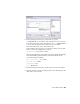

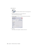


Table Of Contents
- Contents
- Part 1 Tubes and Pipes
- 1 Get Started with Tube & Pipe
- 2 Route Basics
- 3 Set Styles
- 4 Create Rigid Routes and Runs
- Workflow for Rigid Routes
- Create Auto Route Regions
- Manually Create Parametric Regions
- Automatically Dimension Route Sketches
- Create Segments With Precise Values
- Define Parallel and Perpendicular Segments
- Snap Route Points to Existing Geometry
- Place Constraints On Route Sketches
- Create Bends Between Existing Pipe Segments
- Create Pipe Routes With Custom Bends
- Create Bent Tube Routes
- Realign 3D Orthogonal Route Tool
- Control Dimension Visibility
- Populated Routes
- 5 Create and Edit Flexible Hose Routes
- 6 Edit Rigid Routes and Runs
- 7 Use Content Center Libraries
- 8 Author and Publish
- 9 Document Routes and Runs
- Part 2 Cable and Harness
- 10 Get Started with Cable and Harness
- 11 Work With Harness Assemblies
- 12 Use the Cable and Harness Library
- 13 Work with Wires and Cables
- 14 Work with Segments
- 15 Route Wires and Cables
- 16 Work with Splices
- 17 Work with Ribbon Cables
- 18 Generate Reports
- 19 Work With Nailboards and Drawings
- Part 3 IDF Translator
- Index

Practice Your Skills
In this exercise, you learn to recognize the three drawing views you just created.
This will make it easier to recover route centerlines in later exercises.
Move the cursor over the Model browser to highlight each drawing view.
Examine the drawing view structure in the Model browser:
■ The base view (VIEW1) is the parent view of the projected view (VIEW2).
■ The projected view (VIEW2) is the parent view of the detail view (A).
Recover Route Centerlines
By default, the drawing manager hides the centerlines of tube, pipe, and hose
routes in drawing views. Centerline recovery is used to control the availability
of the route centerlines in active tube and pipe drawing views for
dimensioning.
You can control the centerline recovery at the tube and pipe runs assembly,
individual run, or individual route levels in the active drawing view, depending
on the amount of dimensioning you need. For example, when dimensioning
all or most of the routes and runs in a tube and pipe assembly, include route
centerlines for the entire tube and pipe runs assembly, and then hide the
centerlines for the individual runs and routes you do not need.
You must dimension routes to the centerlines in drawing views. Otherwise,
the dimensions may be incorrect. When the specified route centerlines are
recovered, you can dimension routes to the centerlines. If you change the
centerline recovery back, all recovered centerlines in the active drawing views
are deleted so associated dimensions may disappear or become incorrect.
NOTE When a new route or run is created, the route centerline in drawing views
has the same centerline recovery setting as the parent. To add or remove centerlines
for other Autodesk Inventor components in a standard assembly, change the
Automated Centerline Settings on the Tools tab ➤ Options panel ➤ Document
Settings ➤ Drawing tab.
In drawing views that are created from the base view, the route centerline
visibility respects the setting in the base view. For example, if you have
recovered route centerlines in the base view, the relevant route centerlines
are automatically recovered in all associated drawing views that are
subsequently created. When route centerlines are not recovered in the base
view, you can manually recover them for drawing views you need.
Practice Your Skills | 195