
2010


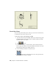
Table Of Contents
- Contents
- Part 1 Tubes and Pipes
- 1 Get Started with Tube & Pipe
- 2 Route Basics
- 3 Set Styles
- 4 Create Rigid Routes and Runs
- Workflow for Rigid Routes
- Create Auto Route Regions
- Manually Create Parametric Regions
- Automatically Dimension Route Sketches
- Create Segments With Precise Values
- Define Parallel and Perpendicular Segments
- Snap Route Points to Existing Geometry
- Place Constraints On Route Sketches
- Create Bends Between Existing Pipe Segments
- Create Pipe Routes With Custom Bends
- Create Bent Tube Routes
- Realign 3D Orthogonal Route Tool
- Control Dimension Visibility
- Populated Routes
- 5 Create and Edit Flexible Hose Routes
- 6 Edit Rigid Routes and Runs
- 7 Use Content Center Libraries
- 8 Author and Publish
- 9 Document Routes and Runs
- Part 2 Cable and Harness
- 10 Get Started with Cable and Harness
- 11 Work With Harness Assemblies
- 12 Use the Cable and Harness Library
- 13 Work with Wires and Cables
- 14 Work with Segments
- 15 Route Wires and Cables
- 16 Work with Splices
- 17 Work with Ribbon Cables
- 18 Generate Reports
- 19 Work With Nailboards and Drawings
- Part 3 IDF Translator
- Index

Create Base Views
Before creating other drawing views, such as projected views and detail views,
you must first create at least one base view.
Create a base view for a tube and pipe assembly
1 Open the AirSystemAssy.iam assembly. Make sure you have the Pipe_Run
design view active for the tube and pipe assembly in which the IBeam
and AirSystem2 are not visible.
2 Click
➤ New.
3 In the New File dialog box select Standard_AIP.idw and then click OK.
The Drawing environment is activated. Examine the Model browser. The
IBeam and Pipe Run 2 have visibility turned off.
4 Save the drawing document as AirSystemAssy.idw.
5
On the ribbon, click Place Views tab ➤ Create panel ➤ Base.
The Drawing View dialog box displays.
188 | Chapter 9 Document Routes and Runs