
2010


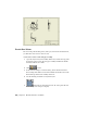
Table Of Contents
- Contents
- Part 1 Tubes and Pipes
- 1 Get Started with Tube & Pipe
- 2 Route Basics
- 3 Set Styles
- 4 Create Rigid Routes and Runs
- Workflow for Rigid Routes
- Create Auto Route Regions
- Manually Create Parametric Regions
- Automatically Dimension Route Sketches
- Create Segments With Precise Values
- Define Parallel and Perpendicular Segments
- Snap Route Points to Existing Geometry
- Place Constraints On Route Sketches
- Create Bends Between Existing Pipe Segments
- Create Pipe Routes With Custom Bends
- Create Bent Tube Routes
- Realign 3D Orthogonal Route Tool
- Control Dimension Visibility
- Populated Routes
- 5 Create and Edit Flexible Hose Routes
- 6 Edit Rigid Routes and Runs
- 7 Use Content Center Libraries
- 8 Author and Publish
- 9 Document Routes and Runs
- Part 2 Cable and Harness
- 10 Get Started with Cable and Harness
- 11 Work With Harness Assemblies
- 12 Use the Cable and Harness Library
- 13 Work with Wires and Cables
- 14 Work with Segments
- 15 Route Wires and Cables
- 16 Work with Splices
- 17 Work with Ribbon Cables
- 18 Generate Reports
- 19 Work With Nailboards and Drawings
- Part 3 IDF Translator
- Index
■ To document individual routes and runs, create design view representations
in which you turn off the visibility of unnecessary components, and then
apply them to appropriate drawing views.
■ Use broken views to fit long nondescript sections of pipe on a drawing.
■ Use detail views to show selected fittings.
■ To dimension routes and runs correctly, recover route centerlines. To
dimension unpopulated routes, you can recover route centerlines.
■ Add the Pipe Length and Stock Number properties to parts lists and a Bill
of Materials table.
■ To create BOMs for specific routes and runs, set their BOM Structure
property to Reference.
Workflow for Documenting Pipe Runs
To document a tube and pipe assembly, you may need to use the following
workflow.
Document a tube and pipe assembly
1 Create a tube and pipe assembly containing populated or unpopulated
routes.
2 Edit design views for the drawing file if you want to output specific views,
especially in some complicated assemblies.
3 Optionally, edit drawing templates.
4 Create one or more base views.
5 Create other required views from the base view or any available parent
views.
6 Recover route centerlines and dimension routes and runs.
7 Create and export the BOMs.
8 Create parts lists.
9 Add balloons to the pipe run components and annotate drawings with
the piping style data.
184 | Chapter 9 Document Routes and Runs