
2010


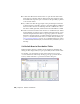


Table Of Contents
- Contents
- Part 1 Tubes and Pipes
- 1 Get Started with Tube & Pipe
- 2 Route Basics
- 3 Set Styles
- 4 Create Rigid Routes and Runs
- Workflow for Rigid Routes
- Create Auto Route Regions
- Manually Create Parametric Regions
- Automatically Dimension Route Sketches
- Create Segments With Precise Values
- Define Parallel and Perpendicular Segments
- Snap Route Points to Existing Geometry
- Place Constraints On Route Sketches
- Create Bends Between Existing Pipe Segments
- Create Pipe Routes With Custom Bends
- Create Bent Tube Routes
- Realign 3D Orthogonal Route Tool
- Control Dimension Visibility
- Populated Routes
- 5 Create and Edit Flexible Hose Routes
- 6 Edit Rigid Routes and Runs
- 7 Use Content Center Libraries
- 8 Author and Publish
- 9 Document Routes and Runs
- Part 2 Cable and Harness
- 10 Get Started with Cable and Harness
- 11 Work With Harness Assemblies
- 12 Use the Cable and Harness Library
- 13 Work with Wires and Cables
- 14 Work with Segments
- 15 Route Wires and Cables
- 16 Work with Splices
- 17 Work with Ribbon Cables
- 18 Generate Reports
- 19 Work With Nailboards and Drawings
- Part 3 IDF Translator
- Index

Keep in mind that you cannot select an edge adjacent to a torus or spline face
to define connection points and connection axes.
■ In the exercises of authoring the pipe iPart, you learn to define connection
points and connection axes using valid circular edges.
■ In the exercises of authoring the 45-degree and 90-degree elbow iParts,
you learn to define connection points and connection axes using existing
work points and work axes that were prepared for the exercises.
In addition, you can use the skills learned from authoring tube and pipe iParts
to author normal parts.
Pipe iPart
In this exercise, you define connection points and connection axes through
valid edges on the sample pipe iPart.
Author a pipe iPart
1 Open the pipe.ipt iPart file.
2 In the Model browser, right-click Table and select Edit via Spread Sheet
or Edit Table to verify the iPart authoring parameters. Close the file.
3 On the ribbon, click Manage tab ➤ Author panel ➤ Tube and Pipe.
4 In the Type list, select Pipe. The default value in the Connections list is
2 and cannot be modified.
5 Verify that connection number button 1 is selected to indicate that you
are setting the information for Connection 1.
6 In the End Treatment list, select Welded for Connection 1.
Author iParts | 167