
2010


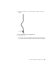


Table Of Contents
- Contents
- Part 1 Tubes and Pipes
- 1 Get Started with Tube & Pipe
- 2 Route Basics
- 3 Set Styles
- 4 Create Rigid Routes and Runs
- Workflow for Rigid Routes
- Create Auto Route Regions
- Manually Create Parametric Regions
- Automatically Dimension Route Sketches
- Create Segments With Precise Values
- Define Parallel and Perpendicular Segments
- Snap Route Points to Existing Geometry
- Place Constraints On Route Sketches
- Create Bends Between Existing Pipe Segments
- Create Pipe Routes With Custom Bends
- Create Bent Tube Routes
- Realign 3D Orthogonal Route Tool
- Control Dimension Visibility
- Populated Routes
- 5 Create and Edit Flexible Hose Routes
- 6 Edit Rigid Routes and Runs
- 7 Use Content Center Libraries
- 8 Author and Publish
- 9 Document Routes and Runs
- Part 2 Cable and Harness
- 10 Get Started with Cable and Harness
- 11 Work With Harness Assemblies
- 12 Use the Cable and Harness Library
- 13 Work with Wires and Cables
- 14 Work with Segments
- 15 Route Wires and Cables
- 16 Work with Splices
- 17 Work with Ribbon Cables
- 18 Generate Reports
- 19 Work With Nailboards and Drawings
- Part 3 IDF Translator
- Index

Change Bend Radius
The radius dimension is displayed for each bend in a tube run by default. You
can change the bend radius for selected nodes in the active route. To edit the
bend radius on individual nodes, you edit dimensions.
Change bend radius on individual nodes
1 Activate Route03 in the AirSystem1:1 run.
2 Double-click the bend radius dimension as shown in the following image.
3 Enter 1.5 inch as the new value, and then click the green check mark.
The radius changes for that node only.
4 Right-click and select Finish Edit.
NOTE Alternatively, you can choose Select Sketch Features from the Select tool
on the Quick Access toolbar while the top-level assembly is activated, and then
double-click the bend radius dimension. Enter the new bend radius, and click
Update.
Change Bend Radius | 145