
2010


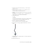


Table Of Contents
- Contents
- Part 1 Tubes and Pipes
- 1 Get Started with Tube & Pipe
- 2 Route Basics
- 3 Set Styles
- 4 Create Rigid Routes and Runs
- Workflow for Rigid Routes
- Create Auto Route Regions
- Manually Create Parametric Regions
- Automatically Dimension Route Sketches
- Create Segments With Precise Values
- Define Parallel and Perpendicular Segments
- Snap Route Points to Existing Geometry
- Place Constraints On Route Sketches
- Create Bends Between Existing Pipe Segments
- Create Pipe Routes With Custom Bends
- Create Bent Tube Routes
- Realign 3D Orthogonal Route Tool
- Control Dimension Visibility
- Populated Routes
- 5 Create and Edit Flexible Hose Routes
- 6 Edit Rigid Routes and Runs
- 7 Use Content Center Libraries
- 8 Author and Publish
- 9 Document Routes and Runs
- Part 2 Cable and Harness
- 10 Get Started with Cable and Harness
- 11 Work With Harness Assemblies
- 12 Use the Cable and Harness Library
- 13 Work with Wires and Cables
- 14 Work with Segments
- 15 Route Wires and Cables
- 16 Work with Splices
- 17 Work with Ribbon Cables
- 18 Generate Reports
- 19 Work With Nailboards and Drawings
- Part 3 IDF Translator
- Index
Adjust Fitting Position and Orientation
Fittings are associated with the underlying route points on the route sketch,
with the exception groups of connected fittings. In this case, the first fitting
placed is associated with an underlying route point and all adjacent fittings
are associated to that first fitting. Repositioning the route point simultaneously
changes the position of the fitting or fitting group. You can activate the route
environment, and then reposition the route point using the 3D Move/Rotate
or General Dimension tool and reposition the default coupling fitting using
the Edit Position or Move Node tool.
You can also use the Edit Fitting Orientation tool to redefine the fitting
orientation and change the connection point.
In this exercise, you change the orientation and connection points on the
fitting you placed in the preceding exercise.
Change fitting orientation and connection point
1 Activate the AirSystem1:1 run.
2 In the graphics window, right-click the cross, and then select Edit Fitting
Orientation.
The 3D Orthogonal Route tool is displayed at the fitting.
3 Use the rotation axes to reorient the fitting.
■ For exact rotation, right-click the rotation arrow, and then select Enter
Angle.
■ For exact position, right-click on the direction axis parallel to the
segment, and then select Enter Distance.
4 Optionally, to change the connection point, right-click in the graphics
window, and then use Select Orientation to set the new connection point.
5 Right-click and select Done.
6 Right-click and select Finish Edit.
Restore Default Fittings
Using the Restore Fitting tool, you can restore the placed fitting to a coupling
or an elbow no matter how many connection points the placed fitting has.
Adjust Fitting Position and Orientation | 135