
2010


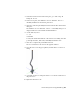


Table Of Contents
- Contents
- Part 1 Tubes and Pipes
- 1 Get Started with Tube & Pipe
- 2 Route Basics
- 3 Set Styles
- 4 Create Rigid Routes and Runs
- Workflow for Rigid Routes
- Create Auto Route Regions
- Manually Create Parametric Regions
- Automatically Dimension Route Sketches
- Create Segments With Precise Values
- Define Parallel and Perpendicular Segments
- Snap Route Points to Existing Geometry
- Place Constraints On Route Sketches
- Create Bends Between Existing Pipe Segments
- Create Pipe Routes With Custom Bends
- Create Bent Tube Routes
- Realign 3D Orthogonal Route Tool
- Control Dimension Visibility
- Populated Routes
- 5 Create and Edit Flexible Hose Routes
- 6 Edit Rigid Routes and Runs
- 7 Use Content Center Libraries
- 8 Author and Publish
- 9 Document Routes and Runs
- Part 2 Cable and Harness
- 10 Get Started with Cable and Harness
- 11 Work With Harness Assemblies
- 12 Use the Cable and Harness Library
- 13 Work with Wires and Cables
- 14 Work with Segments
- 15 Route Wires and Cables
- 16 Work with Splices
- 17 Work with Ribbon Cables
- 18 Generate Reports
- 19 Work With Nailboards and Drawings
- Part 3 IDF Translator
- Index

11 When quitting the AutoDrop, you can right-click the placed fitting and
select Edit Fitting Orientation to display the 3D Orthogonal Route tool
again.
12 Right-click and select Finish Edit.
Practice Your Skills
In this exercise, you use the skills you just learned to insert a pipe part from
the Content Center Library into the background of the graphics window. Note
that you cannot drop the conduit part onto route segments.
In addition to ND (Nominal Diameter), you must specify the SN (Schedule
Number) and PL (Pipe Length) parameters.
Insert a library pipe part
1 Activate the AirSystem1:1 run.
2 Right-click in the graphics window and select the Place from Content
Center tool.
3 In the Place from Content Center dialog box, navigate to and select Tube
& Pipe ➤ Conduits ➤ Pipes ➤ ASTM A 53/A 53M Pipe.
4 In the Content Center Part Family dialog box, specify:
ND: 1/4
SN: 40
PL: 10
5 Click OK.
6 In the Save As dialog box, use the default location and file name.
7 Place the pipe part anywhere in the background of the graphics window.
8 Right-click and select Done.
TIP You can use the Connect Fittings tool to connect the placed tube or pipe
part to another component in the run.
134 | Chapter 6 Edit Rigid Routes and Runs