
2010

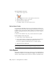


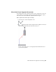
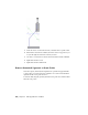


Table Of Contents
- Contents
- Part 1 Tubes and Pipes
- 1 Get Started with Tube & Pipe
- 2 Route Basics
- 3 Set Styles
- 4 Create Rigid Routes and Runs
- Workflow for Rigid Routes
- Create Auto Route Regions
- Manually Create Parametric Regions
- Automatically Dimension Route Sketches
- Create Segments With Precise Values
- Define Parallel and Perpendicular Segments
- Snap Route Points to Existing Geometry
- Place Constraints On Route Sketches
- Create Bends Between Existing Pipe Segments
- Create Pipe Routes With Custom Bends
- Create Bent Tube Routes
- Realign 3D Orthogonal Route Tool
- Control Dimension Visibility
- Populated Routes
- 5 Create and Edit Flexible Hose Routes
- 6 Edit Rigid Routes and Runs
- 7 Use Content Center Libraries
- 8 Author and Publish
- 9 Document Routes and Runs
- Part 2 Cable and Harness
- 10 Get Started with Cable and Harness
- 11 Work With Harness Assemblies
- 12 Use the Cable and Harness Library
- 13 Work with Wires and Cables
- 14 Work with Segments
- 15 Route Wires and Cables
- 16 Work with Splices
- 17 Work with Ribbon Cables
- 18 Generate Reports
- 19 Work With Nailboards and Drawings
- Part 3 IDF Translator
- Index

4 In the Model browser, right-click the Autoroute 1 node and select Convert
to Sketch.
The auto region changes to a series of continuous sketched segments.
Dimensions are added to the route sketch where appropriate.
NOTE If Auto-Dimension is not enabled during route creation, dimensions
will not be added here.
5 Press F8 to verify that all client constraints are deleted so edit options for
parametric regions are available to adjust the route points and segments.
To hide all constraints, press F9.
Convert Auto Region to Parametric Sketch | 127