
2010

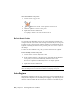


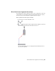


Table Of Contents
- Contents
- Part 1 Tubes and Pipes
- 1 Get Started with Tube & Pipe
- 2 Route Basics
- 3 Set Styles
- 4 Create Rigid Routes and Runs
- Workflow for Rigid Routes
- Create Auto Route Regions
- Manually Create Parametric Regions
- Automatically Dimension Route Sketches
- Create Segments With Precise Values
- Define Parallel and Perpendicular Segments
- Snap Route Points to Existing Geometry
- Place Constraints On Route Sketches
- Create Bends Between Existing Pipe Segments
- Create Pipe Routes With Custom Bends
- Create Bent Tube Routes
- Realign 3D Orthogonal Route Tool
- Control Dimension Visibility
- Populated Routes
- 5 Create and Edit Flexible Hose Routes
- 6 Edit Rigid Routes and Runs
- 7 Use Content Center Libraries
- 8 Author and Publish
- 9 Document Routes and Runs
- Part 2 Cable and Harness
- 10 Get Started with Cable and Harness
- 11 Work With Harness Assemblies
- 12 Use the Cable and Harness Library
- 13 Work with Wires and Cables
- 14 Work with Segments
- 15 Route Wires and Cables
- 16 Work with Splices
- 17 Work with Ribbon Cables
- 18 Generate Reports
- 19 Work With Nailboards and Drawings
- Part 3 IDF Translator
- Index

current style and connection data. It also depends on the geometry adjacent
to the point you select for the operation.
As you drag the selected geometry, the system re-evaluates and updates
adjacent route components. Route points that are automatically generated
between points on selected geometry update when changes are made to a
route.
Move Auto Route Segments Approximately
Using the Move Segment tool on the Route tab, you can move segments in
an auto region approximately. The direction arrows appear on the geometry
indicating the directions allowed for the move. Click anywhere on the segment
near the direction arrow you need, or click and drag the arrow directly. The
arrow changes to red indicating that it is the direction being dragged.
If the minimum length setting for the style is violated during a drag, the
segment or segments in violation turn red. A tooltip also displays the segment
length and the message <Min Pipe Length> in red text.
If alternate solutions are available, the Select Other tool appears for you to
cycle through and select the solution you need.
Move segments in an auto region approximately
1 Activate Route01 in the AirSystem1:1 run.
2
On the ribbon, click Route tab ➤ Create panel ➤ Move
Segment.
3 Pause the cursor over the right end of the segment as shown in the
following image, until the arrow changes to red.
The movement allowed depends on the geometry closest to the point
you select for the drag operation. If the point is a coupling or an associated
route point, the movement is restricted.
Move Auto Route Segments Approximately | 121