
2010
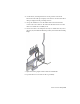


Table Of Contents
- Contents
- Part 1 Tubes and Pipes
- 1 Get Started with Tube & Pipe
- 2 Route Basics
- 3 Set Styles
- 4 Create Rigid Routes and Runs
- Workflow for Rigid Routes
- Create Auto Route Regions
- Manually Create Parametric Regions
- Automatically Dimension Route Sketches
- Create Segments With Precise Values
- Define Parallel and Perpendicular Segments
- Snap Route Points to Existing Geometry
- Place Constraints On Route Sketches
- Create Bends Between Existing Pipe Segments
- Create Pipe Routes With Custom Bends
- Create Bent Tube Routes
- Realign 3D Orthogonal Route Tool
- Control Dimension Visibility
- Populated Routes
- 5 Create and Edit Flexible Hose Routes
- 6 Edit Rigid Routes and Runs
- 7 Use Content Center Libraries
- 8 Author and Publish
- 9 Document Routes and Runs
- Part 2 Cable and Harness
- 10 Get Started with Cable and Harness
- 11 Work With Harness Assemblies
- 12 Use the Cable and Harness Library
- 13 Work with Wires and Cables
- 14 Work with Segments
- 15 Route Wires and Cables
- 16 Work with Splices
- 17 Work with Ribbon Cables
- 18 Generate Reports
- 19 Work With Nailboards and Drawings
- Part 3 IDF Translator
- Index

Options for Editing
You can edit both populated and unpopulated routes. If the route is populated,
activate the route to edit it in place. Library components populating the route
are temporarily set as not visible and the underlying 3D sketch of the route
is displayed.
Route Tab
When you are in the route environment, the Route tab is displayed.
Appropriate tools are available in the specific edit context. Pause the cursor
over the images to view the tooltip.
Pipe Run Tab
When you are in the run environment, the Tube & Pipe tab is displayed. You
can place fittings from the Content Center or your project workspace, and
connect fittings and components.
In the exercises that follow, you learn the basic Connect fitting tools:
Connects two components relative to one another in
a tube and pipe assembly. The components need not
Connect Fittings
be collinear. You can connect a fitting, a conduit part,
or a normal Autodesk Inventor
®
part that already exists
in the assembly to another base component. You can
also connect fittings when placing or dropping them
in the graphics window.
Inserts and connects a new fitting between two connec-
ted fittings in a tube and pipe assembly. The new fitting
Insert Fittings
must be collinear to make the connection. Using this
feature you can build a series of connected fittings, or
insert fittings between fitting groups such as flanges
created during population of a route.
Options for Editing | 113