
2010


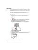


Table Of Contents
- Contents
- Part 1 Tubes and Pipes
- 1 Get Started with Tube & Pipe
- 2 Route Basics
- 3 Set Styles
- 4 Create Rigid Routes and Runs
- Workflow for Rigid Routes
- Create Auto Route Regions
- Manually Create Parametric Regions
- Automatically Dimension Route Sketches
- Create Segments With Precise Values
- Define Parallel and Perpendicular Segments
- Snap Route Points to Existing Geometry
- Place Constraints On Route Sketches
- Create Bends Between Existing Pipe Segments
- Create Pipe Routes With Custom Bends
- Create Bent Tube Routes
- Realign 3D Orthogonal Route Tool
- Control Dimension Visibility
- Populated Routes
- 5 Create and Edit Flexible Hose Routes
- 6 Edit Rigid Routes and Runs
- 7 Use Content Center Libraries
- 8 Author and Publish
- 9 Document Routes and Runs
- Part 2 Cable and Harness
- 10 Get Started with Cable and Harness
- 11 Work With Harness Assemblies
- 12 Use the Cable and Harness Library
- 13 Work with Wires and Cables
- 14 Work with Segments
- 15 Route Wires and Cables
- 16 Work with Splices
- 17 Work with Ribbon Cables
- 18 Generate Reports
- 19 Work With Nailboards and Drawings
- Part 3 IDF Translator
- Index

5 Click to insert the second node.
Move a hose node
1 Right-click the new route point, and select 3D Move/Rotate.
2 Drag the triad in any direction. You can also enter a precise value along
the X, Y, or Z axes.
3 Click Apply or OK.
NOTE If you want to move the hose node that is tangent to the circular edge of
the IBeam, you must right-click the node and clear the Associative check mark.
Redefine a hose node
1 To change the position of the new node, right-click the route point and
select Redefine.
When you move the cursor over planar surfaces or existing work geometry,
the Edit Offset tool appears.
2 Move the cursor to the planar face of the I-Beam.
The offset guide indicates the offset value. By default it is the last selected
offset value or the system default value of 0.440 in for this style.
3 Do either of the following:
■ To use the default offset value, click to set the node.
■ To change the offset value, pause the cursor at an appropriate point,
right-click and select Edit Offset, and then enter a precise value.
The route is recomputed.
4 Right-click and select Done.
Delete a hose node
1 To delete the new route point that you just redefined, right-click the node
and select Delete.
2 Repeat to delete the other inserted route point.
3 After deleting both route points, save the top-level assembly file.
Hose Nodes | 103