
2010


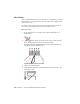
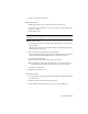


Table Of Contents
- Contents
- Part 1 Tubes and Pipes
- 1 Get Started with Tube & Pipe
- 2 Route Basics
- 3 Set Styles
- 4 Create Rigid Routes and Runs
- Workflow for Rigid Routes
- Create Auto Route Regions
- Manually Create Parametric Regions
- Automatically Dimension Route Sketches
- Create Segments With Precise Values
- Define Parallel and Perpendicular Segments
- Snap Route Points to Existing Geometry
- Place Constraints On Route Sketches
- Create Bends Between Existing Pipe Segments
- Create Pipe Routes With Custom Bends
- Create Bent Tube Routes
- Realign 3D Orthogonal Route Tool
- Control Dimension Visibility
- Populated Routes
- 5 Create and Edit Flexible Hose Routes
- 6 Edit Rigid Routes and Runs
- 7 Use Content Center Libraries
- 8 Author and Publish
- 9 Document Routes and Runs
- Part 2 Cable and Harness
- 10 Get Started with Cable and Harness
- 11 Work With Harness Assemblies
- 12 Use the Cable and Harness Library
- 13 Work with Wires and Cables
- 14 Work with Segments
- 15 Route Wires and Cables
- 16 Work with Splices
- 17 Work with Ribbon Cables
- 18 Generate Reports
- 19 Work With Nailboards and Drawings
- Part 3 IDF Translator
- Index

10 Rotate the assembly as shown in the following image.
11 Pause the cursor over the planar face of the IBeam, right-click and select
Edit Offset. The default offset distance is half the size of the outside
diameter (OD) of the hose part, 0.440 inch for this style.
Create Hose Routes With One Fitting | 99