
2010
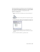


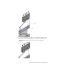


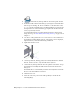
Table Of Contents
- Contents
- Part 1 Tubes and Pipes
- 1 Get Started with Tube & Pipe
- 2 Route Basics
- 3 Set Styles
- 4 Create Rigid Routes and Runs
- Workflow for Rigid Routes
- Create Auto Route Regions
- Manually Create Parametric Regions
- Automatically Dimension Route Sketches
- Create Segments With Precise Values
- Define Parallel and Perpendicular Segments
- Snap Route Points to Existing Geometry
- Place Constraints On Route Sketches
- Create Bends Between Existing Pipe Segments
- Create Pipe Routes With Custom Bends
- Create Bent Tube Routes
- Realign 3D Orthogonal Route Tool
- Control Dimension Visibility
- Populated Routes
- 5 Create and Edit Flexible Hose Routes
- 6 Edit Rigid Routes and Runs
- 7 Use Content Center Libraries
- 8 Author and Publish
- 9 Document Routes and Runs
- Part 2 Cable and Harness
- 10 Get Started with Cable and Harness
- 11 Work With Harness Assemblies
- 12 Use the Cable and Harness Library
- 13 Work with Wires and Cables
- 14 Work with Segments
- 15 Route Wires and Cables
- 16 Work with Splices
- 17 Work with Ribbon Cables
- 18 Generate Reports
- 19 Work With Nailboards and Drawings
- Part 3 IDF Translator
- Index

2 On the ribbon, click Pipe Run tab ➤ Content panel ➤ Place.
3 In the Place from Content Center dialog box, navigate to and double-click
Tube & Pipe ➤ Fittings ➤ Tees ➤ ASME B16.11 Tee Threaded - Class
3000 to open the part family. Select a nominal diameter of 1/2 inch, and
then place the tee on the downward pipe segment in the threaded steel
route you previously created.
For detailed instructions on placing fittings from the Content Center
using AutoDrop, see
Insert Library Parts Using AutoDrop on page 132 in
Chapter 6.
4 Use the 3D Orthogonal Route tool to rotate the tee to the orientation as
shown in the following image. If the 3D Orthogonal tool is not displayed,
right-click the tee, and select Edit Fitting Orientation.
5 Right-click and select Done.
6 On the Pipe Run tab, Manage panel, select the Hydraulic Hose- Female
Thread - Swivel (1/2 ND 1) style from the Active Style list.
7 On the ribbon, click Pipe Run tab ➤ Route panel ➤ New Route. Accept
the default hose assembly file name and location in the Create Hose
dialog box.
The Flexible Hose 02 subassembly is added to the AirSystem1:1 run. The
Hose02 route environment is activated.
8 Click the Route tool.
9 Select the start route point on the same geometry as shown in the
following image.
98 | Chapter 5 Create and Edit Flexible Hose Routes