
2010
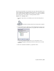


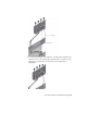


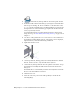
Table Of Contents
- Contents
- Part 1 Tubes and Pipes
- 1 Get Started with Tube & Pipe
- 2 Route Basics
- 3 Set Styles
- 4 Create Rigid Routes and Runs
- Workflow for Rigid Routes
- Create Auto Route Regions
- Manually Create Parametric Regions
- Automatically Dimension Route Sketches
- Create Segments With Precise Values
- Define Parallel and Perpendicular Segments
- Snap Route Points to Existing Geometry
- Place Constraints On Route Sketches
- Create Bends Between Existing Pipe Segments
- Create Pipe Routes With Custom Bends
- Create Bent Tube Routes
- Realign 3D Orthogonal Route Tool
- Control Dimension Visibility
- Populated Routes
- 5 Create and Edit Flexible Hose Routes
- 6 Edit Rigid Routes and Runs
- 7 Use Content Center Libraries
- 8 Author and Publish
- 9 Document Routes and Runs
- Part 2 Cable and Harness
- 10 Get Started with Cable and Harness
- 11 Work With Harness Assemblies
- 12 Use the Cable and Harness Library
- 13 Work with Wires and Cables
- 14 Work with Segments
- 15 Route Wires and Cables
- 16 Work with Splices
- 17 Work with Ribbon Cables
- 18 Generate Reports
- 19 Work With Nailboards and Drawings
- Part 3 IDF Translator
- Index
When modifying the nominal diameter in the style:
■ If the part family (hose, start fitting, and end fitting) contains the member
with the desired nominal diameter, Tube & Pipe automatically locates the
member listed under Components in the Tube & Pipe Styles dialog box.
■ If the part family does not contain the member with the desired nominal
diameter, you must search for and locate them. Under Components,
right-click the appropriate row and select Browse to start the Library Browser
tool, and then select one from the compatible parts list.
Change nominal diameters of hose route components
1 Activate the Hose 01 route in the AirSystem2:1 run.
2 On the ribbon, click Route tab ➤ Manage panel ➤ Tube and Pipe Styles.
Verify that the Hydraulic Hose- Female Thread - Swivel (1/2 ND 2) style
is active.
3 On the General tab, change the Diameter from 1/2 in to 5/16 inches.
4 Verify the list in the Components table. If Pipe, Start Fitting, or End
Fitting is empty, click Browse, and then search for and locate a part from
the compatible parts list.
5 Click Save.
6 Click Close.
7 Right-click and select Finish Edit.
The new diameter applies to the start fitting, hose segment, and end
fitting in the hose route. Autodesk Inventor Tube & Pipe recomputes the
hose route.
Create Hose Routes With One Fitting
In this exercise, you place a threaded tee onto the threaded steel pipe you
previously created, and create a hose route using the Hydraulic Hose- Female
Thread - Swivel (1/2 ND 1) style. This flexible hose style suppresses the end
fitting so the hose route ends at the tee. The fitting is set as suppressed in the
style definition.
Create a hose route
1 Activate the AirSystem1:1 run.
Create Hose Routes With One Fitting | 97