
2010
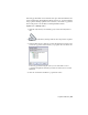


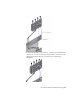


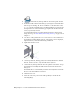
Table Of Contents
- Contents
- Part 1 Tubes and Pipes
- 1 Get Started with Tube & Pipe
- 2 Route Basics
- 3 Set Styles
- 4 Create Rigid Routes and Runs
- Workflow for Rigid Routes
- Create Auto Route Regions
- Manually Create Parametric Regions
- Automatically Dimension Route Sketches
- Create Segments With Precise Values
- Define Parallel and Perpendicular Segments
- Snap Route Points to Existing Geometry
- Place Constraints On Route Sketches
- Create Bends Between Existing Pipe Segments
- Create Pipe Routes With Custom Bends
- Create Bent Tube Routes
- Realign 3D Orthogonal Route Tool
- Control Dimension Visibility
- Populated Routes
- 5 Create and Edit Flexible Hose Routes
- 6 Edit Rigid Routes and Runs
- 7 Use Content Center Libraries
- 8 Author and Publish
- 9 Document Routes and Runs
- Part 2 Cable and Harness
- 10 Get Started with Cable and Harness
- 11 Work With Harness Assemblies
- 12 Use the Cable and Harness Library
- 13 Work with Wires and Cables
- 14 Work with Segments
- 15 Route Wires and Cables
- 16 Work with Splices
- 17 Work with Ribbon Cables
- 18 Generate Reports
- 19 Work With Nailboards and Drawings
- Part 3 IDF Translator
- Index

5 The workflow differs depending on the hose fitting definition that is
specified in the flexible hose style. If the route contains:
■ Both start and end fittings, connect the start fitting and end fitting,
and then add optional intermediate hose nodes.
■ A start fitting, connect the start fitting first, add optional intermediate
hose nodes, and then select the end geometry or component.
■ No fittings (both are suppressed), select the start geometry or
component, add optional intermediate hose nodes, and then select
the end geometry or component.
6 Optionally, edit hose nodes and hose length.
7 Finish the edit and populate the route.
Create Flexible Hose Routes
With a flexible hose style active, click Pipe Run tab ➤ Route panel ➤ New
Route to define a new hose assembly.
Many tools and guides used for creating hose routes are the same as those
used for piping and tubing routes, such as the 3D Orthogonal Route tool and
direction axes. For more information, see
3D Orthogonal Route Tool on page
23 in Chapter 2.
You can insert intermediate nodes in the 3D hose spline. Valid points for
intermediate flexible hose nodes are the same as those for rigid routes. In
addition, you can select points offset from a face. For more information, see
Route Points on page 22 in Chapter 2. Route points created by selecting
arbitrary points offset from a face are not associative and do not update to
changes in the model geometry.
NOTE Once a 3D hose spline is finished by right-clicking and selecting Done, you
can only insert intermediate nodes onto the spline.
Although flexible route fittings are typically connected to other fittings in the
active route or an adjacent route, several types of points are available for
selection. Valid fitting connection points include:
■ A connection on other tube and pipe fittings
92 | Chapter 5 Create and Edit Flexible Hose Routes