
2009


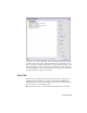


Table Of Contents
- Contents
- Tubes and Pipes
- 1 Getting Started with Tube & Pipe
- 2 Route Basics
- 3 Setting Styles
- 4 Creating Rigid Routes and Runs
- General Workflow for Rigid Routes
- Creating Auto Route Regions
- Manually Creating Parametric Regions
- Automatically Dimension Route Sketches
- Create Segments With Precise Values
- Define Parallel and Perpendicular Segments
- Snap Route Points to Existing Geometry
- Place Constraints On Route Sketches
- Create Bends Between Existing Pipe Segments
- Create Pipe Routes With Custom Bends
- Create Bent Tube Routes
- Realign 3D Orthogonal Route Tool
- Control Dimension Visibility
- Populated Routes
- 5 Creating and Editing Flexible Hose Routes
- 6 Editing Rigid Routes and Runs
- 7 Using Content Center Libraries
- 8 Authoring and Publishing
- 9 Documenting Routes and Runs
- Cable and Harness
- 10 Getting Started with Cable and Harness
- 11 Working With Harness Assemblies
- 12 Using the Cable and Harness Library
- 13 Working with Wires and Cables
- About Wires and Cables
- Setting Modeling and Curvature Behavior
- Inserting Wires and Cables Manually
- Moving Wires and Cables
- Deleting Wires and Cables
- Replacing Wires
- Assigning Virtual Parts
- Importing Harness Data
- Adding Shape to Wires and Cable Wires
- Setting Occurrence Properties
- Changing Wire and Cable Displays
- 14 Working with Segments
- 15 Routing Wires and Cables
- 16 Working with Splices
- 17 Working with Ribbon Cables
- 18 Generating Reports
- 19 Working Nailboards and Drawings
- IDF Translator
- Index

2 On the panel bar, click the Tube & Pipe Styles tool.
3 In the style browser, select ASTM A53/A53M - ASME B16.11 Welded Steel
Pipe as the basis for the new style.
4 Click Copy.
5 From the styles browser, select the copy you just created.
6 Click Edit.
7 On the General tab, enter Welded Steel Pipe - ASTM A53/A53M - ASME B16.11
(1/4 ND) in the Name input box.
NOTE As you create new style definitions, you can also create categories in
which to organize them. Categories are optional.
8 Under Components, notice that there are 4 components included in this
style that have all been successfully selected.
9 Under Diameter, click the arrow to select a nominal diameter of 1/4 in.
from the list.
10 If desired, click the Rules tab to view the settings for minimum and
maximum values and the increment round-off.
11 Click Save.
The new style is added to the browser list, but is not set as the active style
for forward route creation.
12 To set the style as active, right-click the style in the browser list and select
Active.
13 To define the second style, make a copy of ISO 7598/ISO 49 Threaded
Steel Pipe with Iron Fittings.
14 Select and then edit the copy you just created.
15 Name the new style: Threaded Steel Pipe with Iron Fittings (1/2 ND, 90 Only).
16 Under Components, right-click the Elbow 45 row and select Clear.
17 Under Diameter, select a nominal diameter of 1/2 in.
18 Click Save.
44 | Chapter 3 Setting Styles