
2009


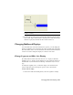


Table Of Contents
- Contents
- Tubes and Pipes
- 1 Getting Started with Tube & Pipe
- 2 Route Basics
- 3 Setting Styles
- 4 Creating Rigid Routes and Runs
- General Workflow for Rigid Routes
- Creating Auto Route Regions
- Manually Creating Parametric Regions
- Automatically Dimension Route Sketches
- Create Segments With Precise Values
- Define Parallel and Perpendicular Segments
- Snap Route Points to Existing Geometry
- Place Constraints On Route Sketches
- Create Bends Between Existing Pipe Segments
- Create Pipe Routes With Custom Bends
- Create Bent Tube Routes
- Realign 3D Orthogonal Route Tool
- Control Dimension Visibility
- Populated Routes
- 5 Creating and Editing Flexible Hose Routes
- 6 Editing Rigid Routes and Runs
- 7 Using Content Center Libraries
- 8 Authoring and Publishing
- 9 Documenting Routes and Runs
- Cable and Harness
- 10 Getting Started with Cable and Harness
- 11 Working With Harness Assemblies
- 12 Using the Cable and Harness Library
- 13 Working with Wires and Cables
- About Wires and Cables
- Setting Modeling and Curvature Behavior
- Inserting Wires and Cables Manually
- Moving Wires and Cables
- Deleting Wires and Cables
- Replacing Wires
- Assigning Virtual Parts
- Importing Harness Data
- Adding Shape to Wires and Cable Wires
- Setting Occurrence Properties
- Changing Wire and Cable Displays
- 14 Working with Segments
- 15 Routing Wires and Cables
- 16 Working with Splices
- 17 Working with Ribbon Cables
- 18 Generating Reports
- 19 Working Nailboards and Drawings
- IDF Translator
- Index

NOTE The wire stubs in this harness are short. If the wire stubs are important in
your nailboard drawings, you can return to the harness assembly and move the
final segment point farther from the connectors. Longer wire stubs are more visible
in the drawing. The drawing updates automatically the next time it is opened or
activated for editing.
Manually arrange individual wire stubs
1 Zoom in on the end of the branched segment to see the distribution of
the wire stubs.
2 Click and drag each of the wire endpoints to change their positions as
shown.
A pivot point is not required when rotating wires about a segment
endpoint.
Automatically arrange multiple wire stubs (fan in and fan out)
1 Right-click the segment endpoint or any of the four wire endpoints, and
then select Fan In/Out ➤ Fan In.
The wires are displayed using the color and diameter of the segment and
the length of the longest wire.
NOTE If a loom is assigned to a wire or segment, they can display using the
color of the loom or the wire. Color style must be set using the Wires/Cables
and Segments tabs of the Harness Settings dialog box before creating the
nailboard.
Arrange the Wire Stubs | 349