
2009


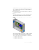

Table Of Contents
- Contents
- Tubes and Pipes
- 1 Getting Started with Tube & Pipe
- 2 Route Basics
- 3 Setting Styles
- 4 Creating Rigid Routes and Runs
- General Workflow for Rigid Routes
- Creating Auto Route Regions
- Manually Creating Parametric Regions
- Automatically Dimension Route Sketches
- Create Segments With Precise Values
- Define Parallel and Perpendicular Segments
- Snap Route Points to Existing Geometry
- Place Constraints On Route Sketches
- Create Bends Between Existing Pipe Segments
- Create Pipe Routes With Custom Bends
- Create Bent Tube Routes
- Realign 3D Orthogonal Route Tool
- Control Dimension Visibility
- Populated Routes
- 5 Creating and Editing Flexible Hose Routes
- 6 Editing Rigid Routes and Runs
- 7 Using Content Center Libraries
- 8 Authoring and Publishing
- 9 Documenting Routes and Runs
- Cable and Harness
- 10 Getting Started with Cable and Harness
- 11 Working With Harness Assemblies
- 12 Using the Cable and Harness Library
- 13 Working with Wires and Cables
- About Wires and Cables
- Setting Modeling and Curvature Behavior
- Inserting Wires and Cables Manually
- Moving Wires and Cables
- Deleting Wires and Cables
- Replacing Wires
- Assigning Virtual Parts
- Importing Harness Data
- Adding Shape to Wires and Cable Wires
- Setting Occurrence Properties
- Changing Wire and Cable Displays
- 14 Working with Segments
- 15 Routing Wires and Cables
- 16 Working with Splices
- 17 Working with Ribbon Cables
- 18 Generating Reports
- 19 Working Nailboards and Drawings
- IDF Translator
- Index

For this exercise, you assign the Wire ID label you created previously to a wire
pin.
Assign a label to a wire pin
1 Activate Harness Assembly1, expand the harness part in the browser to
see the Wires folder.
2 Right-click Pin 6 (6 RefDes U3) and select Wire Pin Properties from the
context menu.
3 On the Wire Pin Properties dialog box, click the Virtual Parts tab and set
the following:
Type: Label
Category: None
Name: Wire ID Label
4 Click Add, and then OK.
Importing Harness Data
Use Import Harness Data on the Cable & Harness panel bar to add (connect)
multiple wires or cables in the harness assembly automatically. You can create
these files yourself using a text editor or spreadsheet, or you can import this
data from other applications such as AutoCAD
®
Electrical. You can import
The import many times with the same or different import files.
NOTE When importing from AutoCAD Electrical, refer to the AutoCAD Electrical
Help for tips on preparing your data for use in Cable and Harness.
Import Harness Data tool
To import the wires and cables, select the import files to use. The import files
include a configuration (.cfg) file and a comma separated (.csv) data file or an
.xml file. The data in these files specifies the point-to-point connectivity of
each wire and cable wire. Ribbon cables cannot be included in import files.
The configuration file, which respects the locale-specific list separator, describes
the format of the input .csv data file. An .xml data file combines the
information provided in both the .cfg and .csv file. It can also include
262 | Chapter 13 Working with Wires and Cables