
2009


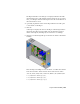

Table Of Contents
- Contents
- Tubes and Pipes
- 1 Getting Started with Tube & Pipe
- 2 Route Basics
- 3 Setting Styles
- 4 Creating Rigid Routes and Runs
- General Workflow for Rigid Routes
- Creating Auto Route Regions
- Manually Creating Parametric Regions
- Automatically Dimension Route Sketches
- Create Segments With Precise Values
- Define Parallel and Perpendicular Segments
- Snap Route Points to Existing Geometry
- Place Constraints On Route Sketches
- Create Bends Between Existing Pipe Segments
- Create Pipe Routes With Custom Bends
- Create Bent Tube Routes
- Realign 3D Orthogonal Route Tool
- Control Dimension Visibility
- Populated Routes
- 5 Creating and Editing Flexible Hose Routes
- 6 Editing Rigid Routes and Runs
- 7 Using Content Center Libraries
- 8 Authoring and Publishing
- 9 Documenting Routes and Runs
- Cable and Harness
- 10 Getting Started with Cable and Harness
- 11 Working With Harness Assemblies
- 12 Using the Cable and Harness Library
- 13 Working with Wires and Cables
- About Wires and Cables
- Setting Modeling and Curvature Behavior
- Inserting Wires and Cables Manually
- Moving Wires and Cables
- Deleting Wires and Cables
- Replacing Wires
- Assigning Virtual Parts
- Importing Harness Data
- Adding Shape to Wires and Cable Wires
- Setting Occurrence Properties
- Changing Wire and Cable Displays
- 14 Working with Segments
- 15 Routing Wires and Cables
- 16 Working with Splices
- 17 Working with Ribbon Cables
- 18 Generating Reports
- 19 Working Nailboards and Drawings
- IDF Translator
- Index

Wire color changes take effect immediately. To see the effect of changes to
outer diameter values, click the Update tool.
Replace a wire
1 Activate Harness Assembly1.
2 In the browser or graphics window, select Wire1, right-click, and then
select Edit Wire.
NOTE To select the wire in the graphics window, you may need to set the
Select tool to Select sketch elements.
3 On the Edit Wire dialog box select:
Category: Belden
Name: 9916-V10
4 If necessary, click Properties to view the properties for the library wire.
5 To redraw the wire using the new definition, click Apply, and then Cancel.
The wire in the graphics window is redrawn in violet.
6 Return the wire to the original, green wire definition. On the Edit Wire
dialog box, select:
Category: Generic
Name: 22AWG-GRN
7 Click OK.
NOTE Cables cannot be replaced. Delete them and add them again with
the appropriate cable chosen from the library list.
Assigning Virtual Parts
You can assign virtual parts to various objects in a harness assembly using the
Assign Virtual Parts tool on the Cable & Harness panel bar. You can also assign
virtual parts to individual objects through the Property dialog box of an object.
You can use one of the virtual parts in the Cable and Harness Library, or you
can create and use your own. Refer to the Tube & Pipe Help for information
on types of virtual parts that may be assigned to various harness object types.
Assigning Virtual Parts | 261