
2009


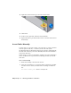


Table Of Contents
- Contents
- Tubes and Pipes
- 1 Getting Started with Tube & Pipe
- 2 Route Basics
- 3 Setting Styles
- 4 Creating Rigid Routes and Runs
- General Workflow for Rigid Routes
- Creating Auto Route Regions
- Manually Creating Parametric Regions
- Automatically Dimension Route Sketches
- Create Segments With Precise Values
- Define Parallel and Perpendicular Segments
- Snap Route Points to Existing Geometry
- Place Constraints On Route Sketches
- Create Bends Between Existing Pipe Segments
- Create Pipe Routes With Custom Bends
- Create Bent Tube Routes
- Realign 3D Orthogonal Route Tool
- Control Dimension Visibility
- Populated Routes
- 5 Creating and Editing Flexible Hose Routes
- 6 Editing Rigid Routes and Runs
- 7 Using Content Center Libraries
- 8 Authoring and Publishing
- 9 Documenting Routes and Runs
- Cable and Harness
- 10 Getting Started with Cable and Harness
- 11 Working With Harness Assemblies
- 12 Using the Cable and Harness Library
- 13 Working with Wires and Cables
- About Wires and Cables
- Setting Modeling and Curvature Behavior
- Inserting Wires and Cables Manually
- Moving Wires and Cables
- Deleting Wires and Cables
- Replacing Wires
- Assigning Virtual Parts
- Importing Harness Data
- Adding Shape to Wires and Cable Wires
- Setting Occurrence Properties
- Changing Wire and Cable Displays
- 14 Working with Segments
- 15 Routing Wires and Cables
- 16 Working with Splices
- 17 Working with Ribbon Cables
- 18 Generating Reports
- 19 Working Nailboards and Drawings
- IDF Translator
- Index

A dangling wire can also be moved to reattach detached ends to existing pins.
Spare cable wires, cable wires that have no connections, can also be attached
to pins, including splice pins.
Moving Wires
To move a wire, choose the wire to move, select Edit Wire from the context
menu, click the selection button representing the pin connection to change,
and then select the new pin connection. In this exercise, you move Pin 2 of
the wire you added previously to another pin on the same connector.
Move a wire
1 Activate Harness Assembly1.
2 In the browser or graphics window, right-click Wire1, and then select
Edit Wire from the context menu.
NOTE To select the pin in the graphics window, you may need to set the
Select tool to Select sketch features.
3 On the Edit Wire dialog box, verify the Pin 1 button is selected.
4 In the graphics window, move the cursor over the pins to preview the
wire connection possibilities before making a selection.
The preview wire is a straight white line drawn between the two pins.
5 When the tooltip is displayed as U3 Pin 6, click the pin as shown in the
following illustration.
Moving Wires | 257