
2009


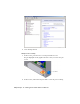

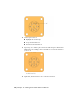


Table Of Contents
- Contents
- Tubes and Pipes
- 1 Getting Started with Tube & Pipe
- 2 Route Basics
- 3 Setting Styles
- 4 Creating Rigid Routes and Runs
- General Workflow for Rigid Routes
- Creating Auto Route Regions
- Manually Creating Parametric Regions
- Automatically Dimension Route Sketches
- Create Segments With Precise Values
- Define Parallel and Perpendicular Segments
- Snap Route Points to Existing Geometry
- Place Constraints On Route Sketches
- Create Bends Between Existing Pipe Segments
- Create Pipe Routes With Custom Bends
- Create Bent Tube Routes
- Realign 3D Orthogonal Route Tool
- Control Dimension Visibility
- Populated Routes
- 5 Creating and Editing Flexible Hose Routes
- 6 Editing Rigid Routes and Runs
- 7 Using Content Center Libraries
- 8 Authoring and Publishing
- 9 Documenting Routes and Runs
- Cable and Harness
- 10 Getting Started with Cable and Harness
- 11 Working With Harness Assemblies
- 12 Using the Cable and Harness Library
- 13 Working with Wires and Cables
- About Wires and Cables
- Setting Modeling and Curvature Behavior
- Inserting Wires and Cables Manually
- Moving Wires and Cables
- Deleting Wires and Cables
- Replacing Wires
- Assigning Virtual Parts
- Importing Harness Data
- Adding Shape to Wires and Cable Wires
- Setting Occurrence Properties
- Changing Wire and Cable Displays
- 14 Working with Segments
- 15 Routing Wires and Cables
- 16 Working with Splices
- 17 Working with Ribbon Cables
- 18 Generating Reports
- 19 Working Nailboards and Drawings
- IDF Translator
- Index
Note that each pin name within the selected part is unique. The pin name
specified is also the name of the special work point feature listed in the browser.
Set Part Properties
Specific property data must be added to a part to provide a complete electrical
definition. These properties are also visible on the part occurrence in the
assembly.
The part name and part number are automatically set based on the part file
name and the Autodesk Inventor part number. If appropriate, you can set a
value for the placeholder reference designator property.
The reference designator, or RefDes, is a unique identifier that maps the part
to the schematic design. Typically a placeholder identifier, such as U? is added
in the part environment, and then a specific identifier is added for each
occurrence of the part in the context of the assembly. For example, if a certain
RS232 connector occurs in an assembly multiple times, each occurrence must
have a unique identifier, such as U1, U2, and U3.
Additional custom properties can also be added to the part. Custom properties
provide specific information to downstream processes such as reporting.
Custom properties such as the vendor and vendor part number, often come
from the data book for the component.
To save time on data entry and reduce entry errors, consider creating a template
for electrical parts that contains placeholders for commonly used properties.
Add RefDes Placeholders
In this exercise, you add a placeholder RefDes to the electrical part.
Add a RefDes placeholder
1 With nothing selected, select the Harness Properties tool from the Harness
Part Features panel bar.
Alternatively, right-click the part in the browser, and then select Harness
Properties from the context menu.
2 On the General tab of the Part properties dialog box, enter a reference
designator (RefDes). In this case, enter the placeholder U?.
3 Click OK on the dialog box, and then click OK on the message box.
Set Part Properties | 217