
2009


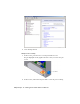

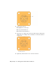


Table Of Contents
- Contents
- Tubes and Pipes
- 1 Getting Started with Tube & Pipe
- 2 Route Basics
- 3 Setting Styles
- 4 Creating Rigid Routes and Runs
- General Workflow for Rigid Routes
- Creating Auto Route Regions
- Manually Creating Parametric Regions
- Automatically Dimension Route Sketches
- Create Segments With Precise Values
- Define Parallel and Perpendicular Segments
- Snap Route Points to Existing Geometry
- Place Constraints On Route Sketches
- Create Bends Between Existing Pipe Segments
- Create Pipe Routes With Custom Bends
- Create Bent Tube Routes
- Realign 3D Orthogonal Route Tool
- Control Dimension Visibility
- Populated Routes
- 5 Creating and Editing Flexible Hose Routes
- 6 Editing Rigid Routes and Runs
- 7 Using Content Center Libraries
- 8 Authoring and Publishing
- 9 Documenting Routes and Runs
- Cable and Harness
- 10 Getting Started with Cable and Harness
- 11 Working With Harness Assemblies
- 12 Using the Cable and Harness Library
- 13 Working with Wires and Cables
- About Wires and Cables
- Setting Modeling and Curvature Behavior
- Inserting Wires and Cables Manually
- Moving Wires and Cables
- Deleting Wires and Cables
- Replacing Wires
- Assigning Virtual Parts
- Importing Harness Data
- Adding Shape to Wires and Cable Wires
- Setting Occurrence Properties
- Changing Wire and Cable Displays
- 14 Working with Segments
- 15 Routing Wires and Cables
- 16 Working with Splices
- 17 Working with Ribbon Cables
- 18 Generating Reports
- 19 Working Nailboards and Drawings
- IDF Translator
- Index

3 In the Model browser, delete work points 1 through 9. You re-create these
points in the next steps.
4
Click the arrow in the Part Features title bar, and then select Harness
Part Features. Click the Place Pin tool.
5 Rotate and zoom the view to see the part as shown in the following image.
Turn visibility off for any parts obstructing your view.
6 In the graphics window, move the cursor over the part geometry to
highlight valid points for your selection.
7 Highlight the circular edge shown, and then click to select the center
point.
8 On the Pin Name dialog box, use the default pin name of 1.
9 Click the Harness Properties button to display the entire Pin Properties
dialog box.
10 Click the Custom tab to see where custom properties are added.
For this exercise, do not add any additional properties for the pin.
11 Click OK.
The work point representing the pin appears for pin 1.
Place Pins and Define Pin-level Properties | 215