
2009


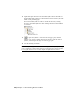


Table Of Contents
- Contents
- Tubes and Pipes
- 1 Getting Started with Tube & Pipe
- 2 Route Basics
- 3 Setting Styles
- 4 Creating Rigid Routes and Runs
- General Workflow for Rigid Routes
- Creating Auto Route Regions
- Manually Creating Parametric Regions
- Automatically Dimension Route Sketches
- Create Segments With Precise Values
- Define Parallel and Perpendicular Segments
- Snap Route Points to Existing Geometry
- Place Constraints On Route Sketches
- Create Bends Between Existing Pipe Segments
- Create Pipe Routes With Custom Bends
- Create Bent Tube Routes
- Realign 3D Orthogonal Route Tool
- Control Dimension Visibility
- Populated Routes
- 5 Creating and Editing Flexible Hose Routes
- 6 Editing Rigid Routes and Runs
- 7 Using Content Center Libraries
- 8 Authoring and Publishing
- 9 Documenting Routes and Runs
- Cable and Harness
- 10 Getting Started with Cable and Harness
- 11 Working With Harness Assemblies
- 12 Using the Cable and Harness Library
- 13 Working with Wires and Cables
- About Wires and Cables
- Setting Modeling and Curvature Behavior
- Inserting Wires and Cables Manually
- Moving Wires and Cables
- Deleting Wires and Cables
- Replacing Wires
- Assigning Virtual Parts
- Importing Harness Data
- Adding Shape to Wires and Cable Wires
- Setting Occurrence Properties
- Changing Wire and Cable Displays
- 14 Working with Segments
- 15 Routing Wires and Cables
- 16 Working with Splices
- 17 Working with Ribbon Cables
- 18 Generating Reports
- 19 Working Nailboards and Drawings
- IDF Translator
- Index

10 Right-click again and select Save Sketched Symbol. Enter the name on
the Sketched Symbol dialog box and click Save. In this exercise, enter the
name Conduit_Standard_Type.
The new sketched symbol is added to the Model browser, Drawing
Resources, Sketched Symbol list. The drawing annotation environment
is activated.
11 To place the symbol to annotate tube and pipe parts, click the
Symbols tool on the Drawing Annotation panel bar, pick the desired
symbol, and then pick an edge on a tube or pipe part.
12 Save the drawing document.
NOTE When placing symbols to annotate drawings, ensure that you pick an edge
on the conduit part or fitting while placing a custom piping style sketched symbol.
To end, right-click and select Continue. Right-click again and select Done.
204 | Chapter 9 Documenting Routes and Runs