
2009
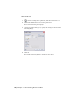


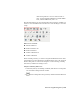


Table Of Contents
- Contents
- Tubes and Pipes
- 1 Getting Started with Tube & Pipe
- 2 Route Basics
- 3 Setting Styles
- 4 Creating Rigid Routes and Runs
- General Workflow for Rigid Routes
- Creating Auto Route Regions
- Manually Creating Parametric Regions
- Automatically Dimension Route Sketches
- Create Segments With Precise Values
- Define Parallel and Perpendicular Segments
- Snap Route Points to Existing Geometry
- Place Constraints On Route Sketches
- Create Bends Between Existing Pipe Segments
- Create Pipe Routes With Custom Bends
- Create Bent Tube Routes
- Realign 3D Orthogonal Route Tool
- Control Dimension Visibility
- Populated Routes
- 5 Creating and Editing Flexible Hose Routes
- 6 Editing Rigid Routes and Runs
- 7 Using Content Center Libraries
- 8 Authoring and Publishing
- 9 Documenting Routes and Runs
- Cable and Harness
- 10 Getting Started with Cable and Harness
- 11 Working With Harness Assemblies
- 12 Using the Cable and Harness Library
- 13 Working with Wires and Cables
- About Wires and Cables
- Setting Modeling and Curvature Behavior
- Inserting Wires and Cables Manually
- Moving Wires and Cables
- Deleting Wires and Cables
- Replacing Wires
- Assigning Virtual Parts
- Importing Harness Data
- Adding Shape to Wires and Cable Wires
- Setting Occurrence Properties
- Changing Wire and Cable Displays
- 14 Working with Segments
- 15 Routing Wires and Cables
- 16 Working with Splices
- 17 Working with Ribbon Cables
- 18 Generating Reports
- 19 Working Nailboards and Drawings
- IDF Translator
- Index

Annotation panel bar. It does not affect features or
parts. You can add general dimensions, baseline dimen-
sions, ordinate dimensions, and so on.
The following image shows the Drawing Annotation panel bar on which you
can use tools to add dimensions. Pause the cursor over the images to view the
tooltip.
Dimension tools include:
■ General Dimension
■ Baseline Dimension Set
■ Baseline Dimension
■ Ordinate Dimension Set
■ Ordinate Dimension
In the following exercises, you learn to add general dimensions in the detail
view DETAIL A. For more information on dimensioning, refer to the Autodesk
Inventor Help table of contents and navigate to Create Drawings, Drawing
Annotations, Dimension Drawings section.
Add general drawing dimensions
1 In the AirSystemAssy.idw drawing document, click the arrow on the panel
bars and click Drawing Annotation Panel.
2
On the Drawing Annotation panel bar, click the General Dimension
tool.
Dimensioning Drawing Views | 195