
2009
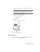

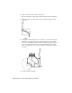


Table Of Contents
- Contents
- Tubes and Pipes
- 1 Getting Started with Tube & Pipe
- 2 Route Basics
- 3 Setting Styles
- 4 Creating Rigid Routes and Runs
- General Workflow for Rigid Routes
- Creating Auto Route Regions
- Manually Creating Parametric Regions
- Automatically Dimension Route Sketches
- Create Segments With Precise Values
- Define Parallel and Perpendicular Segments
- Snap Route Points to Existing Geometry
- Place Constraints On Route Sketches
- Create Bends Between Existing Pipe Segments
- Create Pipe Routes With Custom Bends
- Create Bent Tube Routes
- Realign 3D Orthogonal Route Tool
- Control Dimension Visibility
- Populated Routes
- 5 Creating and Editing Flexible Hose Routes
- 6 Editing Rigid Routes and Runs
- 7 Using Content Center Libraries
- 8 Authoring and Publishing
- 9 Documenting Routes and Runs
- Cable and Harness
- 10 Getting Started with Cable and Harness
- 11 Working With Harness Assemblies
- 12 Using the Cable and Harness Library
- 13 Working with Wires and Cables
- About Wires and Cables
- Setting Modeling and Curvature Behavior
- Inserting Wires and Cables Manually
- Moving Wires and Cables
- Deleting Wires and Cables
- Replacing Wires
- Assigning Virtual Parts
- Importing Harness Data
- Adding Shape to Wires and Cable Wires
- Setting Occurrence Properties
- Changing Wire and Cable Displays
- 14 Working with Segments
- 15 Routing Wires and Cables
- 16 Working with Splices
- 17 Working with Ribbon Cables
- 18 Generating Reports
- 19 Working Nailboards and Drawings
- IDF Translator
- Index

6 Click to set the portion of the projected view.
The cursor changes to a plus symbol. The detail view preview is displayed.
7 Move the cursor to the appropriate position, and then click to set the
detail view.
8 If the portion in the detail view is not as desired, you can use the circular
selection tool to adjust the portion. Move the cursor over the circular
selection tool in VIEW2 as shown in the following image, click to activate
it. To move the circular selection tool, click and drag the green center
point. To change the portion, click and drag the circular edge outward
or inward.
9 Save the drawing document.
192 | Chapter 9 Documenting Routes and Runs