
2009


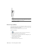
Table Of Contents
- Contents
- Tubes and Pipes
- 1 Getting Started with Tube & Pipe
- 2 Route Basics
- 3 Setting Styles
- 4 Creating Rigid Routes and Runs
- General Workflow for Rigid Routes
- Creating Auto Route Regions
- Manually Creating Parametric Regions
- Automatically Dimension Route Sketches
- Create Segments With Precise Values
- Define Parallel and Perpendicular Segments
- Snap Route Points to Existing Geometry
- Place Constraints On Route Sketches
- Create Bends Between Existing Pipe Segments
- Create Pipe Routes With Custom Bends
- Create Bent Tube Routes
- Realign 3D Orthogonal Route Tool
- Control Dimension Visibility
- Populated Routes
- 5 Creating and Editing Flexible Hose Routes
- 6 Editing Rigid Routes and Runs
- 7 Using Content Center Libraries
- 8 Authoring and Publishing
- 9 Documenting Routes and Runs
- Cable and Harness
- 10 Getting Started with Cable and Harness
- 11 Working With Harness Assemblies
- 12 Using the Cable and Harness Library
- 13 Working with Wires and Cables
- About Wires and Cables
- Setting Modeling and Curvature Behavior
- Inserting Wires and Cables Manually
- Moving Wires and Cables
- Deleting Wires and Cables
- Replacing Wires
- Assigning Virtual Parts
- Importing Harness Data
- Adding Shape to Wires and Cable Wires
- Setting Occurrence Properties
- Changing Wire and Cable Displays
- 14 Working with Segments
- 15 Routing Wires and Cables
- 16 Working with Splices
- 17 Working with Ribbon Cables
- 18 Generating Reports
- 19 Working Nailboards and Drawings
- IDF Translator
- Index

6 On the Drawing View dialog box, Component tab, specify:
File Windows XP: C:\Program Files\Autodesk\Inventor<version>\Design
Data\Tutorial Files\Tube & Pipe\AirSystemAssy.iam. File Windows Vista:
C:\Users\Public\Documents\Autodesk\Inventor<version>\Design
Data\Tutorial Files\Tube & Pipe\AirSystemAssy.iam
If an assembly is already opened, it is selected by default. You can click
Browse to locate the assembly that you need.
Representation: Pipe_Run, Associative
The active design view for the assembly is selected by default. The drawing
view automatically updates when the component visibility in the
associated design view changes.
View / Scale Label: 0.15:1, Visible
View Identifier: VIEW1
Orientation: Front
Style: Hidden Line
7 On the Drawing View dialog box, Display Options tab, use the defaults.
8 Move the preview to the upper-right quadrant of the drawing sheet, and
then click to place the view.
Create Base Views | 187